Measurement adjusting mechanism of jet machining precision equipment

A technology of adjustment mechanism and precision equipment, applied in metal processing equipment, abrasive jet machine tools, measuring devices, etc., can solve the problems of ensuring polishing quality, large deviation between measurement and processing, and insufficient measurement accuracy, and improve processing quality and efficiency. , good reliability, simple and convenient operation

Pending Publication Date: 2021-12-28
GUANGXI UNIV
View PDF0 Cites 0 Cited by
  • Summary
  • Abstract
  • Description
  • Claims
  • Application Information

AI Technical Summary

Problems solved by technology

[0003] In the existing process flow, it is necessary to determine the processing position of the workpiece before spraying the workpiece. At present, some methods are to use the detection system to detect the product to be processed, and collect the image of the product to be processed through the detection system such as a smart camera, etc. Send it to the control device, obtain the position information to be processed through comparative analysis and conversion algorithm, and perform jet processing on the product to be processed according to the detection result, but the measurement accuracy of this detection method is not high enough at present, and it is impossible to perform high-precision control to ensure Polishing quality, and the position of the workpiece often needs to be adjusted in the process of image acquisition, and a more complicated transmission mechanism is required to drive the position adjustment of the workpiece in different dimensions, which may lead to large deviations in measurement and processing

Method used


Image

  • Measurement adjusting mechanism of jet machining precision equipment
  • Measurement adjusting mechanism of jet machining precision equipment
  • Measurement adjusting mechanism of jet machining precision equipment

Examples


Embodiment

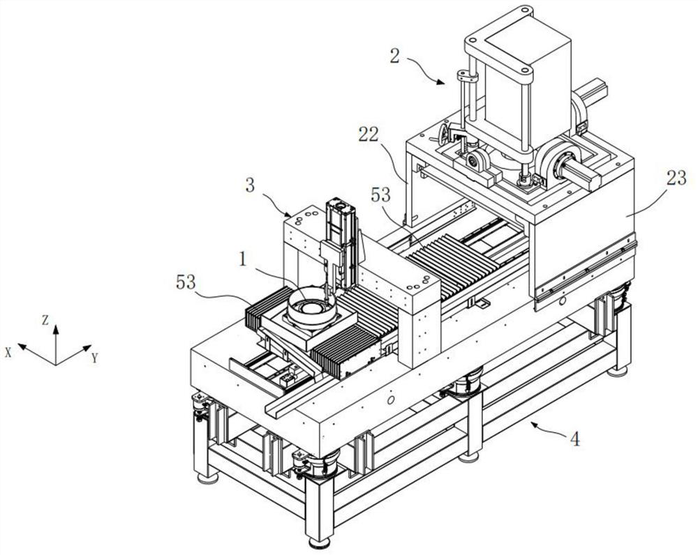
[0022] see figure 1 As shown, a spray processing precision equipment includes a workbench 1 for loading workpieces, a measurement and adjustment mechanism 2 for measuring workpieces, a spray mechanism 3 for spray processing workpieces according to the detection results, and a movement mechanism 4. The workbench 1, the measurement adjustment mechanism 2 and the injection mechanism 3 are all arranged on the movement mechanism 4 and integrated into one body. The movement mechanism 4 can respectively drive the workbench 1 to move back and forth to the bottom of the measurement adjustment mechanism 2 and the injection mechanism 3. The invention also includes a host computer, which is respectively connected with the measurement and adjustment mechanism 2, the injection mechanism 3 and the movement mechanism 4.

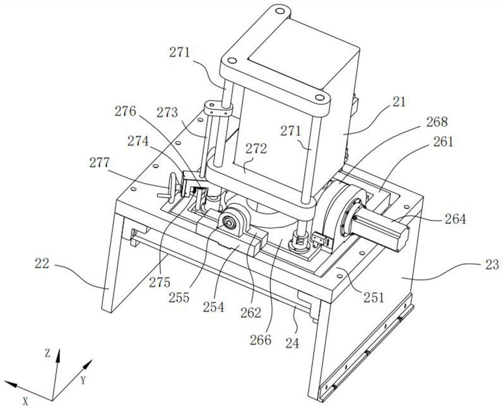
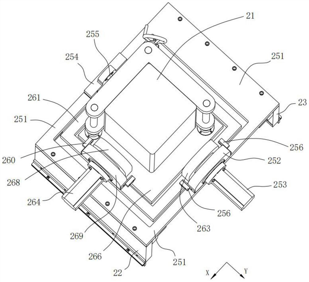
[0023] The measurement adjustment mechanism 2 claimed in the present invention, see Figure 2 to Figure 4 As shown, the measurement adjustment mechanism 2 includes a laser ...


PUM


Abstract

The invention discloses a measurement adjusting mechanism of jet machining precision equipment, which comprises a laser interferometer, an X-axis adjusting frame capable of driving the laser interferometer to rotate around an X axis, a Y-axis adjusting frame capable of driving the laser interferometer to rotate around a Y axis, and a lifting mechanism capable of driving the laser interferometer to lift in a Z-axis direction, the laser interferometer is movably connected to the middle of the X-axis adjusting frame, and the X-axis adjusting frame is movably connected to the middle of the Y-axis adjusting frame. According to the invention, the mode of measuring by adjusting a workpiece in the past is changed into the mode of adjusting the position of the measuring instrument, the operation mode is simpler and more efficient, the detection and processing quality and efficiency are improved, the reliability is good, and the measurement adjusting mechanism is suitable for precision processing.

Description

technical field [0001] The invention relates to an equipment device for performing abrasive jet finishing on the surface of a workpiece, in particular to a measuring and adjusting mechanism part in the jet processing equipment. Background technique [0002] Abrasive water jet polishing technology is to use the polishing liquid mixed with fine abrasive particles sprayed at high speed from the nozzle to act on the surface of the workpiece, and achieve the purpose of grinding and removing materials through the high-speed collision and shearing of abrasives. , Angle and injection time and other process parameters to modify the polishing process of the surface roughness of the workpiece. [0003] In the existing process flow, it is necessary to determine the processing position of the workpiece before spraying the workpiece. At present, some methods are to use the detection system to detect the product to be processed, and collect the image of the product to be processed through ...

Claims


Application Information

Patent Timeline
Patent Type & Authority Applications(China)
IPC IPC(8): G01B9/02B24C1/08B24C3/02B24C9/00
CPCG01B9/02B24C1/08B24C3/02B24C9/00
Inventor 梁旭斌尤辉陈旭红潘海鸿
Owner GUANGXI UNIV
Why Eureka
Try Eureka