A Horizontal Omnidirectional Circularly Polarized Antenna

A technology of circularly polarized antenna and polarized antenna, which is applied to antennas, antenna parts, and devices that make antennas work in different frequency bands at the same time, can solve the problems of high cost, large diameter, and difficulty in combining antenna gains with high gains, etc. Achieve the effect of light weight, simple structure and high reliability

Active Publication Date: 2022-03-11
陕西海积信息科技有限公司
View PDF16 Cites 0 Cited by
  • Summary
  • Abstract
  • Description
  • Claims
  • Application Information

AI Technical Summary

Problems solved by technology

[0002] Antenna is a device used to radiate and receive electromagnetic waves in radio equipment. It is one of the indispensable components of radio communication, radar, navigation, remote sensing, telemetry, radio astronomy and electronic countermeasures. There are two polarization methods for satellite receiving antennas. Type: one is linear polarization, the other is circular polarization; among them, under the line polarization mode, it is divided into horizontal polarization and vertical polarization; the existing horizontal omnidirectional circular polarization antenna adopts clover, four-leaf To achieve circular polarization in the form of grass, the antenna gain is difficult to synthesize high gain; or the circularly polarized array antenna is placed in a complex ring with a centimeter network, the diameter is relatively large, and the cost is relatively high

Method used


Image

  • A Horizontal Omnidirectional Circularly Polarized Antenna
  • A Horizontal Omnidirectional Circularly Polarized Antenna
  • A Horizontal Omnidirectional Circularly Polarized Antenna

Examples


Embodiment

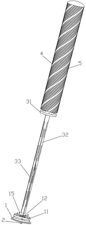
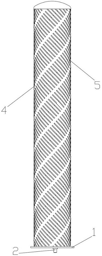
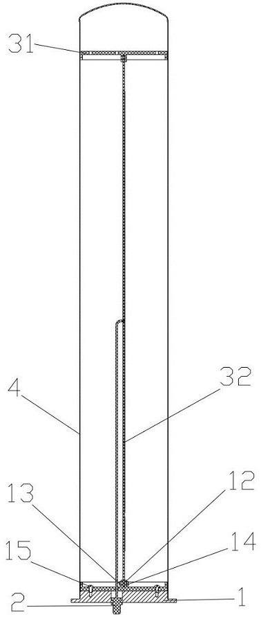
[0025] see Figure 1-4 As shown, a horizontal omnidirectional circularly polarized antenna provided by the embodiment of the present invention includes a base plate 1, an output connector 2 disposed on the lower end of the base plate 1, a vertically polarized antenna 3 disposed on the upper end of the base plate 1, and a vertically polarized antenna 3 disposed on the base plate 1. The upper end is sleeved on the polarized radome 4 outside the vertically polarized antenna 3. The output connector 2 passes through the bottom plate 1 and is connected to the vertically polarized antenna 3. The shape of the polarized radome 4 is a hollow tube, and the vertically polarized The antenna 3 is located at the axial center of the polarized radome 4, and the outer surface of the polarized radome 4 is obliquely covered with a plurality of metal polarization grids 5, and the plurality of metal polarization grids 5 are arranged in sequence and form a grid-like spiral Spin up.

[0026] Through...


PUM


Abstract

The invention discloses a horizontal omnidirectional circularly polarized antenna, which comprises a base plate, an output connector disposed at the lower end of the base plate, a vertically polarized antenna disposed at the upper end of the base plate, and a vertically polarized antenna disposed at the upper end of the base plate and sheathed outside the vertically polarized antenna Polarized radome, the output connector passes through the bottom plate upwards and connects with the vertically polarized antenna, the shape of the polarized radome is a hollow tube, the vertically polarized antenna is located at the axis of the polarized radome, the The outer surface is obliquely covered with a plurality of metal polarization grids, which are arranged in sequence and spirally rotated in the shape of a grid; through the spiral metal polarization grid, the linearly polarized electromagnetic wave can be converted into a circular pole. The electromagnetic waves of the polarization form a light-weight, high-reliability high-gain horizontal omnidirectional circularly polarized antenna, which realizes circularly polarized characteristics with a very simple structure.

Description

technical field [0001] The invention belongs to the field of antennas, in particular to a horizontal omnidirectional circularly polarized antenna. Background technique [0002] Antenna is a device used to radiate and receive electromagnetic waves in radio equipment. It is one of the indispensable components of radio communication, radar, navigation, remote sensing, telemetry, radio astronomy and electronic countermeasures. There are two polarization methods for satellite receiving antennas. Type: one is linear polarization, the other is circular polarization; among them, under the line polarization mode, it is divided into horizontal polarization and vertical polarization; the existing horizontal omnidirectional circular polarization antenna adopts clover, four-leaf If circular polarization is realized in the form of grass, the antenna gain is difficult to synthesize high gain; or the antenna with circularly polarized elements placed in a ring with a relatively complex centi...

Claims


Application Information

Patent Timeline
Patent Type & Authority Patents(China)
IPC IPC(8): H01Q1/42H01Q15/24H01Q5/28H01Q5/30
CPCH01Q1/425H01Q15/244H01Q5/28H01Q5/30
Inventor 冯维星王鹏张伟伟王冠君朱良谢亚运吴兴军卫俊
Owner 陕西海积信息科技有限公司
Why Eureka
Try Eureka