Supercharge Your Innovation With Domain-Expert AI Agents!

An electric heating structure for the rotor of a pyrolysis equipment

A technology of electric heating and electric heating elements, applied in the direction of ohmic resistance heating parts, heating elements, etc., can solve the problems of wire rotation or shaking, wire influence heat dissipation, and large safety hazards, so as to reduce the possibility of cable damage and facilitate Removal and installation, reduce the effect of cable damage

Active Publication Date: 2022-05-24
CHINA ERZHONG GRP DEYANG HEAVY IND
View PDF18 Cites 0 Cited by
  • Summary
  • Abstract
  • Description
  • Claims
  • Application Information

AI Technical Summary

Problems solved by technology

[0003] Existing pyrolysis equipment with electric heating as the main heating method, its main heating component is the heating rotor, the heating rotor includes a rotor disk, and many electric heating elements are arranged in the rotor disk, so more wires are needed for electric heating. The element supplies power, and because the electric heating element will rotate with the rotor disk, the wire will rotate or shake with the rotation of the rotor disk, which is prone to winding and friction. If the wire is entangled, the heating rotor will not be able to continue to rotate , causing failure; if friction occurs, the insulation layer of the wire is easily damaged, and the safety hazard is relatively large; and because of the high temperature, too many wires will affect heat dissipation, making the wire easy to heat up and be destroyed by temperature rise; the above problems make the It is very difficult to connect the electric heating element with the power supply, which is an engineering problem that needs to be solved urgently

Method used


Image

  • An electric heating structure for the rotor of a pyrolysis equipment
  • An electric heating structure for the rotor of a pyrolysis equipment
  • An electric heating structure for the rotor of a pyrolysis equipment

Examples


Embodiment 1

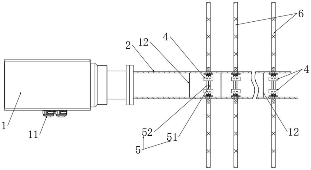
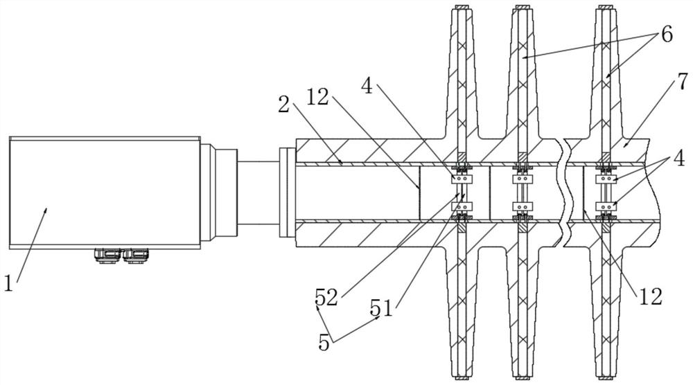
[0051] This embodiment provides an electric heating structure for the rotor of a pyrolysis equipment, see Figure 1-3 , including a rotor disc 7, the rotor disc 7 is distributed with several circles of electric heating zones in the axial direction, and a number of electric heating elements 6 are distributed in the circumferential direction of the electric heating zone, and one end of the electric heating element 6 is penetrated to the In the core hole of the rotor disc 7,

[0052] The electric heating structure further includes a hollow shaft 2, the hollow shaft 2 is arranged along the axial direction of the rotor disk 7, the outer wall of the hollow shaft 2 is adjacent to the inner wall of the core hole, and one end of the hollow shaft 2 is fixedly connected The rotating part of the slip ring box 1, the fixed part of the slip ring box 1 is connected to an external power supply, and a number of ring rows 5 are installed inside the hollow shaft 2 along its axial interval, and e...

Embodiment 2

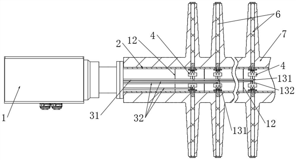
[0070] This embodiment provides an electric heating structure for the rotor of a pyrolysis equipment, which is different from Embodiment 1 in that, such as Figure 10 As shown, each of the neutral wire loops 51 is connected to the rotating part through a cable one 31 , and each live wire loop 52 is electrically connected to the rotating part through a cable two 32 .

[0071] In this solution, each ring row 5 needs to be connected with two cables, that is, the live wire ring 52 needs a cable 2 to 32 connection, and the neutral wire ring 51 needs a cable 1 to 31 connection. In this way, the communication of an external power source with the electric heating element 6 can also be achieved. By dislocating the cable one 31 connected to the neutral wire ring 51 and the cable two 32 connected to the live wire ring 52 in the hollow shaft 2, the installation space is provided, and the cable one 31 and the cable are lowered. Two 32 the possibility of mutual interference.

[0072] As a...


PUM


Abstract

The invention relates to an electric heating structure of a pyrolysis equipment rotor. By setting a hollow shaft on the inner wall of the core hole of the rotor disk as an installation basis, the ring row can be installed corresponding to the electric heating area; the electric heating element can be connected by setting the ring row , can reduce the number of required cables, improve heat dissipation, reduce the possibility of friction, and reduce the possibility of cable damage; there are sockets corresponding to the electric heating elements on the ring row, which are easy to disassemble, install and replace; The ring box cooperates with the ring row to connect the power supply and the electric heating element, which can realize the static and dynamic conversion of the cable, so that the cable, the ring row, the socket, the electric heating element and the rotor disc rotate together, and the cable will not be entangled, so that the rotor disc can Keep turning. The connection between the electric heating element and the power supply is safe and stable, and it can continue to heat without interfering with the rotation of the rotor disk, so that the heating rotor pyrolysis equipment with electric heating as the main heating method can be realized.

Description

technical field [0001] The invention relates to the technical field of pyrolysis equipment, in particular to an electric heating structure for a rotor of a pyrolysis equipment. Background technique [0002] At present, there are various heating methods in pyrolysis technology, such as open flame heating, high temperature flue gas heating, electromagnetic heating, microwave heating, hammer mill heating, and heat transfer oil heating. It will cause secondary pollution, some of them are not safe, some of the equipment is more complicated and the investment is high and the operating cost is high. The pyrolysis equipment with electric heating as the main heating method has the advantages of high efficiency, high standard, high safety and environmental protection. [0003] In the existing pyrolysis equipment with electric heating as the main heating method, its main heating component is a heating rotor, and the heating rotor includes a rotor disc. Many electric heating elements a...

Claims


Application Information

Patent Timeline
Patent Type & Authority Patents(China)
IPC IPC(8): H05B3/06H05B3/02
CPCH05B3/06H05B3/02
Inventor 刘胜涛江浩周大云杨静豪杨闽
Owner CHINA ERZHONG GRP DEYANG HEAVY IND
Features
  • R&D
  • Intellectual Property
  • Life Sciences
  • Materials
  • Tech Scout
  • Unparalleled Data Quality
  • Higher Quality Content
  • 60% Fewer Hallucinations
Learn More