Supercharge Your Innovation With Domain-Expert AI Agents!

Sludge discharge device for sewage treatment and use method

A sludge discharge device and sewage treatment technology, which is applied in water/sludge/sewage treatment, sludge treatment, dehydration/drying/concentrated sludge treatment, etc., and can solve the problems of rust of equipment parts and large amount of sludge discharge. , to achieve the effect of prolonging service life, thorough sludge adsorption and reducing workload

Pending Publication Date: 2021-12-31
青海天普伟业环保科技有限公司
View PDF6 Cites 0 Cited by
  • Summary
  • Abstract
  • Description
  • Claims
  • Application Information

AI Technical Summary

Problems solved by technology

[0003] However, the advection sedimentation tank is used for mud discharge. In the prior art, mud hoppers and mud discharge pipes are used to discharge mud. As a result, each mud hopper needs to be equipped with a separate mud discharge pipe for mud discharge. The workload of mud discharge is large, and the use of Mechanical mud discharge also leads to long-term immersion of machinery equipment and driving parts in water, causing rust problems in equipment parts

Method used


Image

  • Sludge discharge device for sewage treatment and use method
  • Sludge discharge device for sewage treatment and use method
  • Sludge discharge device for sewage treatment and use method

Examples


Embodiment 1

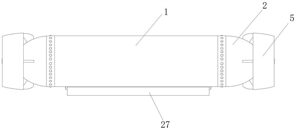
[0044] Embodiment one, according to Figure 1-Figure 6 , through the control of the control terminal 13, the water pump 15 is controlled to act, and at the same time, the first electric control valve 7, the second electric control valve 16 and the fourth electric control valve 20 are controlled to close, and the fifth electric control valve 31 and the third electric control valve 31 are opened. The valve 29 introduces the water above the sedimentation tank into the counterweight box 18 to make the tank 1 sink into the water. At the same time, the control terminal 13 starts the heating pipe 19 for heating. When the tank 1 is placed on the top of the sludge, the control terminal 13 controls to close The fifth electric control valve 31 and the third electric control valve 29 open the first electric control valve 7 and the fourth electric control valve 20, and start the sludge pump 6, and use the sludge pump 6 to pass the sludge at the bottom of the pool through the suction nozzle ...

Embodiment 2

[0045] Embodiment two, according to Figure 4 and Figure 7 , through the action of the output end of the electric cylinder 26, the baffle plate 27 is driven to swing, and through the swing of the baffle plate 27, the shifting block 28 is used to move, and the sludge is loosened with the relative movement of the shifting block 28, and then through the rotation of the paddle 4, water is realized. Downward stirring, through the strengthening of the stirring action and the swing of the toggle device 14, the sludge at the bottom is stirred to effectively deal with the stubborn contact between the sludge and the bottom of the tank, so that the sludge is more thoroughly adsorbed.

[0046] A method for using a sludge discharge device for sewage treatment, the steps of the method are as follows:

[0047] 1. Start the control terminal, put the tank in the water, control the water pump through the control terminal, close the first electric control valve 7, the second electric control v...


PUM


Abstract

The invention discloses a sludge discharge device for sewage treatment and a use method. The sludge discharge device comprises a cabin cylinder, power cabins are welded at two ends of the cabin cylinder, driving motors are mounted in the power cabins, the driving motors extend to the outside of the power cabins and are provided with paddles, protective covers are mounted on the outer surfaces of the power cabins, a sludge pump is installed at one end in the cabin cylinder, the input end of the sludge pump is provided with the output end of a first electric control valve, and the input end of the first electric control valve communicates with an input pipe. Sludge discharge treatment is performed in a submersible sludge suction manner, and compared with the prior art, a sludge bucket and a sludge discharge pipe do not need to be matched for each horizontal-flow sedimentation tank, so that the workload is greatly reduced, after sludge discharge is completed, only each sludge discharge device needs to be fished, and treated sludge solids are directly taken out from the interior of a cabin body after being fished, and can be directly transported and subjected to subsequent treatment. Meanwhile, the sludge discharge device does not need to be placed in water for a long time and can be regularly maintained, so that the service life is prolonged.

Description

technical field [0001] The invention relates to the technical field of sludge treatment, in particular to a sludge discharge device for sewage treatment and a use method thereof. Background technique [0002] The advection sedimentation tank consists of three parts: the inlet and outlet, the water flow part and the sludge bucket. The plane of the pool body is rectangular, and the inlet and outlet are respectively set at both ends of the pool. The inlet generally adopts the submerged water inlet hole, and the water flows into the pool body through the evenly distributed water inlet holes from the inlet channel. There is a baffle behind the water inlet hole to make the water flow Evenly distributed across the entire width of the pool; overflow weirs are often used at the outlet to ensure that the clarified water after sedimentation can flow into the outlet channel evenly along the width of the pool. A scum tank and a baffle are arranged in front of the weir to intercept the s...

Claims


Application Information

Patent Timeline
Patent Type & Authority Applications(China)
IPC IPC(8): B01D21/24C02F11/13C02F11/00
CPCB01D21/2461C02F11/13C02F11/004
Inventor 徐波苏国梁付国明李发林王顺基鲁文选雷有慧王树孝刘发平阎宁马进虎东占祥关雪健文丕燕王积祥何云刘玮萍王芳辛羽陈英
Owner 青海天普伟业环保科技有限公司
Features
  • R&D
  • Intellectual Property
  • Life Sciences
  • Materials
  • Tech Scout
  • Unparalleled Data Quality
  • Higher Quality Content
  • 60% Fewer Hallucinations
Learn More