
Tool for precisely cutting bolted U-rib hand hole

A precision cutting, hand hole technology, applied in welding equipment, manufacturing tools, metal processing equipment, etc., can solve the problems of cutting size and verticality out of tolerance, and achieve the effect of low tooling cost, guaranteeing stability, and guaranteeing use accuracy

Pending Publication Date: 2021-12-31
中铁宝桥(扬州)有限公司 +2
View PDF0 Cites 0 Cited by
  • Summary
  • Abstract
  • Description
  • Claims
  • Application Information

AI Technical Summary

Problems solved by technology

[0003] Aiming at the technical problems existing in the above-mentioned background technology, the present invention proposes a structure design that is simple and reasonable, easy to operate and use, and can realize the precise cutting of the position and size of the U-rib hand hole where the steel box girder plate unit is bolted to the U-rib, and can Tooling for precision cutting of bolted U-rib hand holes that effectively solves the problem of cutting size and verticality out-of-tolerance problems caused by existing methods such as manual lofting and cutting

Method used


Image

  • Tool for precisely cutting bolted U-rib hand hole
  • Tool for precisely cutting bolted U-rib hand hole
  • Tool for precisely cutting bolted U-rib hand hole

Examples


Embodiment Construction

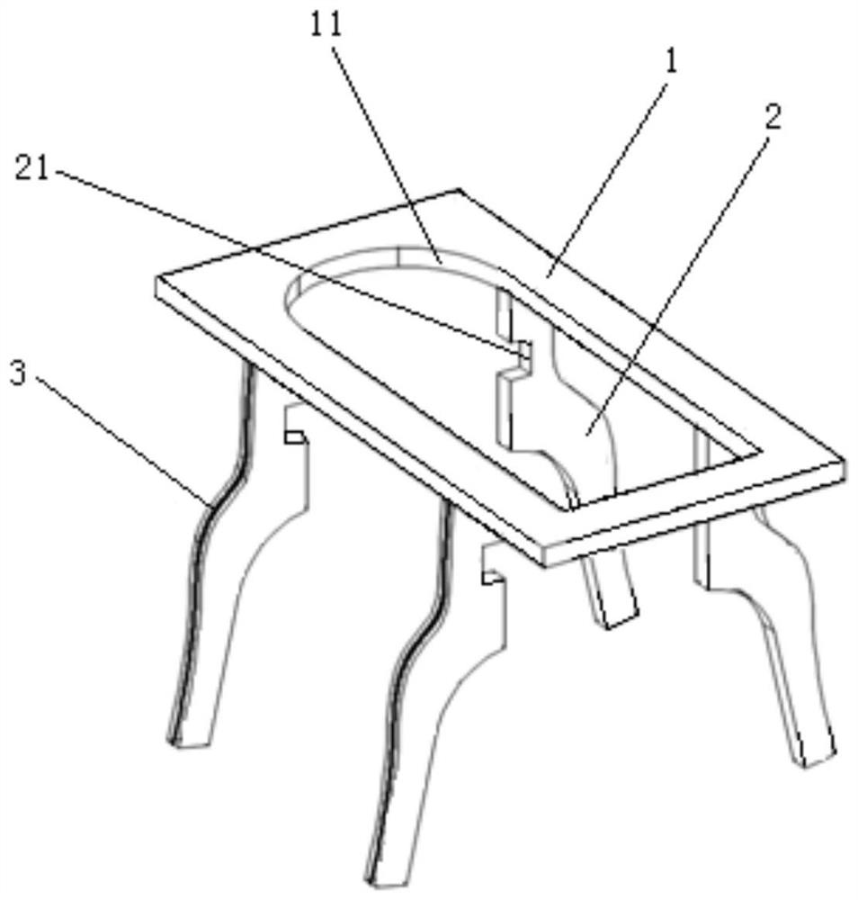
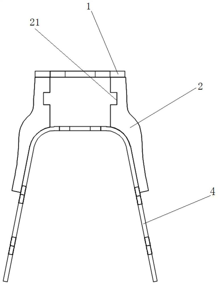
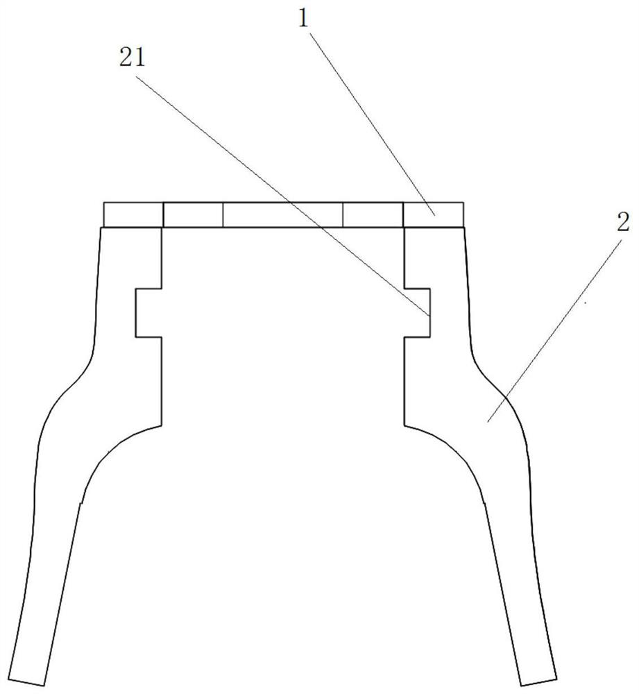
[0022] like Figures 1 to 6 As shown, the tooling of the present invention for bolting U-rib hand hole precision cutting includes a profiling model 1 and a support plate 2 .

[0023] The profiling sample 1 is a rectangular plate structure, which is arranged horizontally and kept parallel to the U rib 4 of the steel box girder plate unit; Through hole 11, and the inner hole wall at one end of the longitudinal direction of the profiling through hole 11 is a semicircle, and the inner contour of the profiling through hole 11 is on the same cutting plane as the U rib hand hole 41

[0024] There are four support plates 2, which are matched and symmetrically welded vertically on the left and right sides of the bottom of the profiling template 1 in groups of two. The side of each support plate 2 facing the U rib 4 of the steel box girder plate unit is an inner section, and each The side of the four supporting plates 2 facing away from the U rib 4 of the steel box girder plate unit is...


PUM

PropertyMeasurementUnit
thicknessaaaaaaaaaa

Abstract

The invention relates to a tool for precisely cutting a bolted U-rib hand hole. The tool comprises a profiling sample plate and supporting plates. The profiling sample plate is horizontally arranged and is parallel to the U-rib of a steel box girder plate unit up and down. A profiling through hole matched with the U-rib hand hole of the U-rib of the steel box girder plate unit in size is formed in the middle area of the profiling sample plate in a matched and penetrating mode, and the inner contour of the profiling through hole and the U-rib hand hole are located on the same cutting face. The supporting plates are symmetrically fixed to the two opposite sides of the bottom of the profiling sample plate in a matched mode. The surfaces, facing the U-rib of the steel box girder plate unit, of the supporting plates are completely and tightly attached to the outer wall of the U-rib of the steel box girder plate unit in a matched mode, and the surfaces, back on to the U-rib of the steel box girder plate unit, of the supporting plates are provided with positioning datum lines in a matched mode. The tool is simple and reasonable in structural design and convenient to operate and use, accurate cutting of the position and size of the U-rib hand hole of the U-rib of the steel box beam plate unit can be achieved, and the problem that the cutting size and perpendicularity are out of tolerance due to existing manual lofting cutting methods and the like can be effectively solved.

Description

technical field [0001] The invention belongs to the technical field of steel bridge processing and manufacturing, and in particular relates to a tool for precision cutting of bolted U-rib hand holes. Background technique [0002] With the rapid development of steel structure bridges in my country, long-span steel box girder bridges are gradually increasing, and the quality of orthotropic steel bridge decks has become the focus of steel box girder disease control. U-rib is an important part of orthotropic plate, the processing method and quality control are particularly critical. At present, the arc hand hole at the end of the U rib is commonly used for manual lofting and scribing cutting and CNC equipment cutting; among them, the manual lofting and scribing cutting is done by the workers on site, and then use the flame cutting torch to cut according to the line. If there is deviation in the scribing line or The vibration during cutting, cutting size and verticality will not...

Claims


Application Information

Patent Timeline
Patent Type & Authority Applications(China)
IPC IPC(8): B23K7/10B23K7/00
CPCB23K7/105B23K7/00
Inventor 谷文吴江波薛宏强陈正凯马敬博
Owner 中铁宝桥(扬州)有限公司
Learn More