
Detachable saturated submersible pressure cabin footing limiting mechanism and using method thereof

A technology of restricting mechanism and pressure chamber, which is applied in the direction of transportation and packaging, underwater operation equipment, hull, etc., can solve the problems of high construction cost, difficult reinstallation, low work efficiency, etc., to meet the gap accuracy requirements, reduce time, and facilitate Effects of installation and post-maintenance

Active Publication Date: 2021-12-31
广州黄船海洋工程有限公司
View PDF5 Cites 0 Cited by
  • Summary
  • Abstract
  • Description
  • Claims
  • Application Information

AI Technical Summary

Problems solved by technology

Two kinds of limiting blocks are used, and the quantity is large; these two kinds of limiting blocks are installed by welding. After welding, the deformation of the limiting block itself due to welding is far greater than the gap accuracy requirement, and the clearance of the limiting block at the foot of the cabin cannot be guaranteed. Accuracy; when rework and modification are required, both of these two limiting blocks need to be cut and disassembled, and it is extremely difficult to reinstall, with low work efficiency and high construction costs

Method used


Image

  • Detachable saturated submersible pressure cabin footing limiting mechanism and using method thereof
  • Detachable saturated submersible pressure cabin footing limiting mechanism and using method thereof
  • Detachable saturated submersible pressure cabin footing limiting mechanism and using method thereof

Examples


Embodiment Construction

[0032] The following will clearly and completely describe the technical solutions in the embodiments of the present invention with reference to the accompanying drawings in the embodiments of the present invention. Obviously, the described embodiments are only some, not all, embodiments of the present invention. Based on the embodiments of the present invention, all other embodiments obtained by persons of ordinary skill in the art without creative efforts fall within the protection scope of the present invention.

[0033] In the description of the present invention, it should be noted that the terms "center", "upper", "lower", "left", "right", "vertical", "horizontal", "inner", "outer" etc. The indicated orientation or positional relationship is based on the orientation or positional relationship shown in the drawings, and is only for the convenience of describing the present invention and simplifying the description, rather than indicating or implying that the referred device...


PUM


Abstract

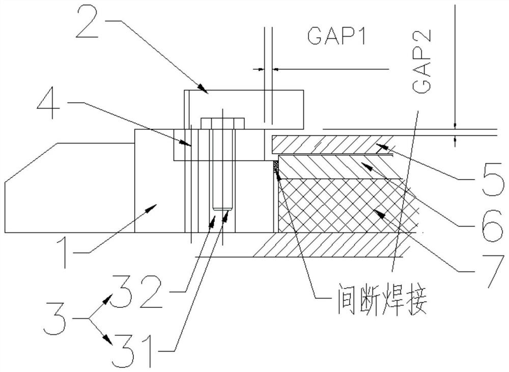
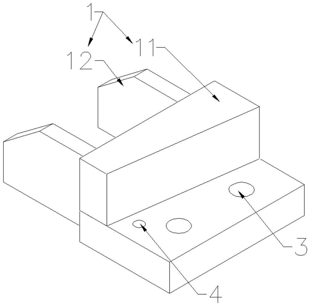
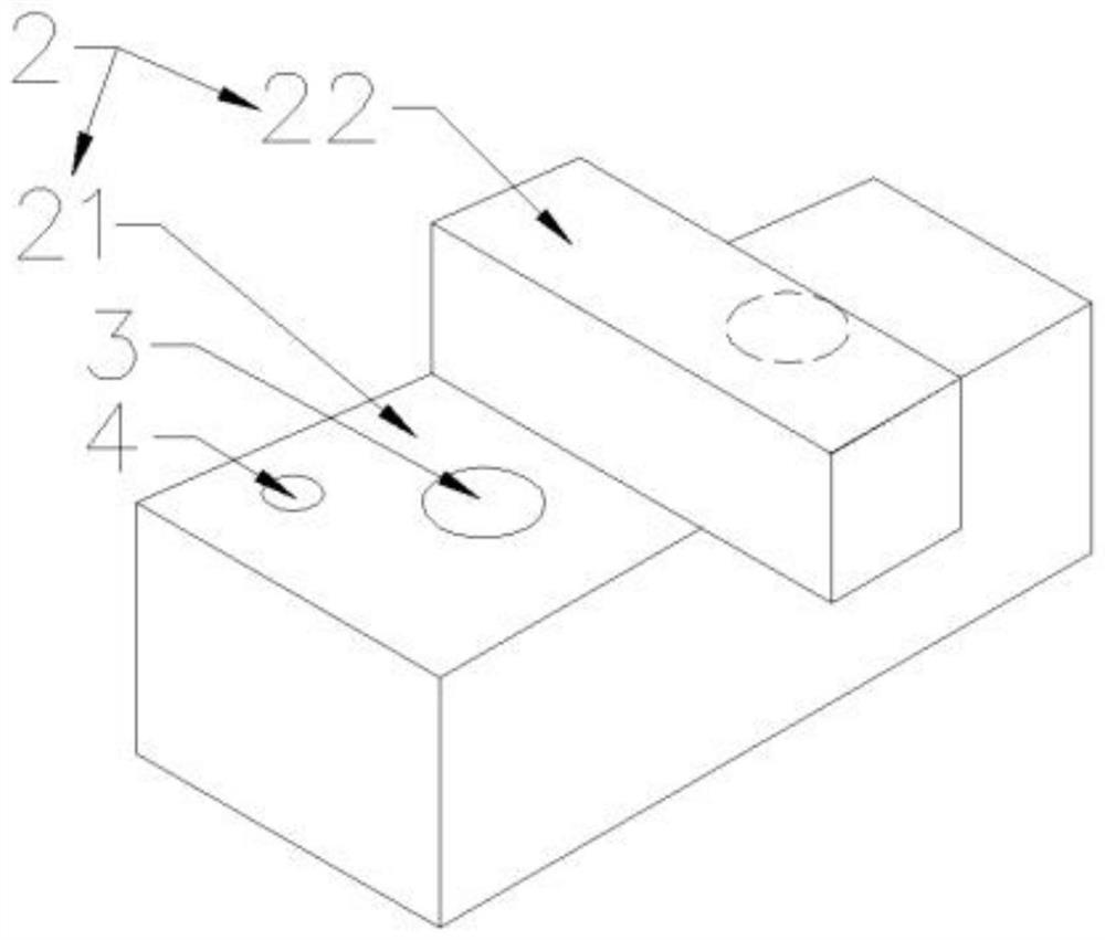
The invention discloses a detachable saturated submersible pressure cabin footing limiting mechanism and a using method thereof. The detachable saturated submersible pressure cabin footing limiting mechanism comprises a detachable adjusting block and a detachable fixing block, the fixing block comprises a step-shaped fixing base, the adjusting block comprises a horizontal limiting block and a vertical limiting block, the horizontal limiting block is detachably fixed to a step of the fixing base through a connecting piece, and one side of the horizontal limiting block is attached to the vertical surface of the upper step of the fixing base so as to limit the left-right movement of a cabin footing; and the vertical limiting block is fixed to the horizontal limiting block, and the end, away from the vertical face of the upper step of the fixing base, of the vertical limiting block exceeds the horizontal limiting block to limit vertical movement of the cabin footing. The influence of welding deformation on the precision of an adjusting block can be effectively avoided, and installation and later maintenance are facilitated; and the adjusting block can be independently disassembled and then reassembled after being machined, so that the time is greatly shortened, and the clearance precision requirement of long-term use of equipment is met.

Description

technical field [0001] The invention relates to the technical field of diving system equipment installation, in particular to a detachable foot restricting mechanism of a saturated diving pressure chamber and a use method thereof. Background technique [0002] The saturation diving pressure chamber is the core equipment of the saturation diving system, and the pressure in the pressure chamber can be adjusted according to the working water depth. The shape of the pressure chamber is a cylindrical capsule cavity. As the internal pressure changes, the volume of the pressure chamber will change slightly, so the foot support of the pressure chamber will also move left and right and up and down with the change of pressure. At present, the bottom foot of the saturated diving pressure chamber uses a foot restriction mechanism to restrict its left and right movement and up and down movement. There are two types of existing design foot restriction mechanisms. Limit blocks for left an...

Claims


Application Information

Patent Timeline
IPC IPC(8): B63C11/00B63B3/14
CPCB63C11/00B63B3/14
Inventor 刘崇喆谢文汉马金金万超徐波
Owner 广州黄船海洋工程有限公司
Learn More