Flushing executing mechanism for vacuum closestool

A technology of an actuator and a vacuum toilet, which is applied to flushing equipment with water tanks, cabin flushing devices, flushing toilets, etc., can solve the problems of vacuum toilet volume limitation, increase equipment volume, limited space, etc., to reduce occupied space and disassemble Simple maintenance and easy disassembly

Pending Publication Date: 2021-12-31
ZHEJIANG JIANJIANG SHIP TECH CO LTD
View PDF0 Cites 0 Cited by
  • Summary
  • Abstract
  • Description
  • Claims
  • Application Information

AI Technical Summary

Problems solved by technology

The vacuum system is maintained by the automatic operation of the vacuum pump. Generally, the vacuum toilet is formed by the vacuum pump and the actuator to form a pressure difference with the atmospheric pressure to take away the contents of the toilet. At the same time, the actuator will control the opening of the water inlet valve to flush the toilet. It is often used on ships or warships; however, the space on ships or warships is limited, and there are certain restrictions on the volume of vacuum toilets. The existing actuators and water inlet valves are set separately, which increases the volume of the equipment

Method used


Image

  • Flushing executing mechanism for vacuum closestool
  • Flushing executing mechanism for vacuum closestool
  • Flushing executing mechanism for vacuum closestool

Examples


Embodiment Construction

[0024] The present invention will be described in further detail below in conjunction with the accompanying drawings.

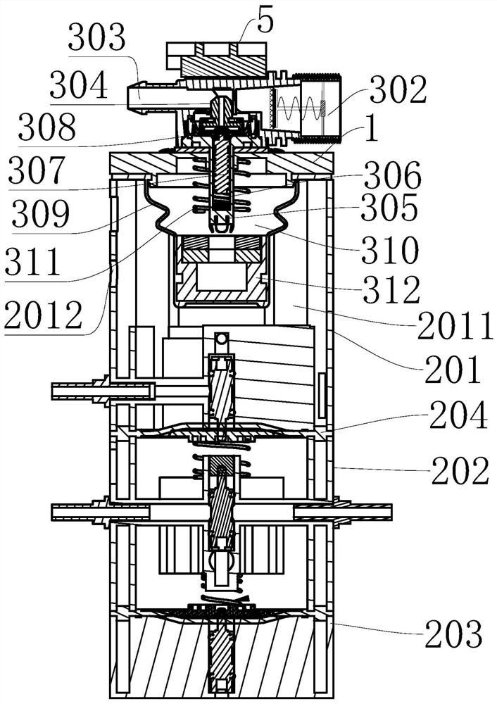
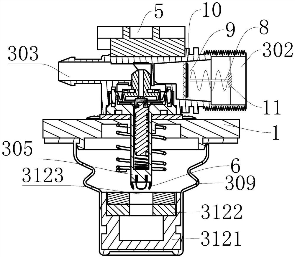
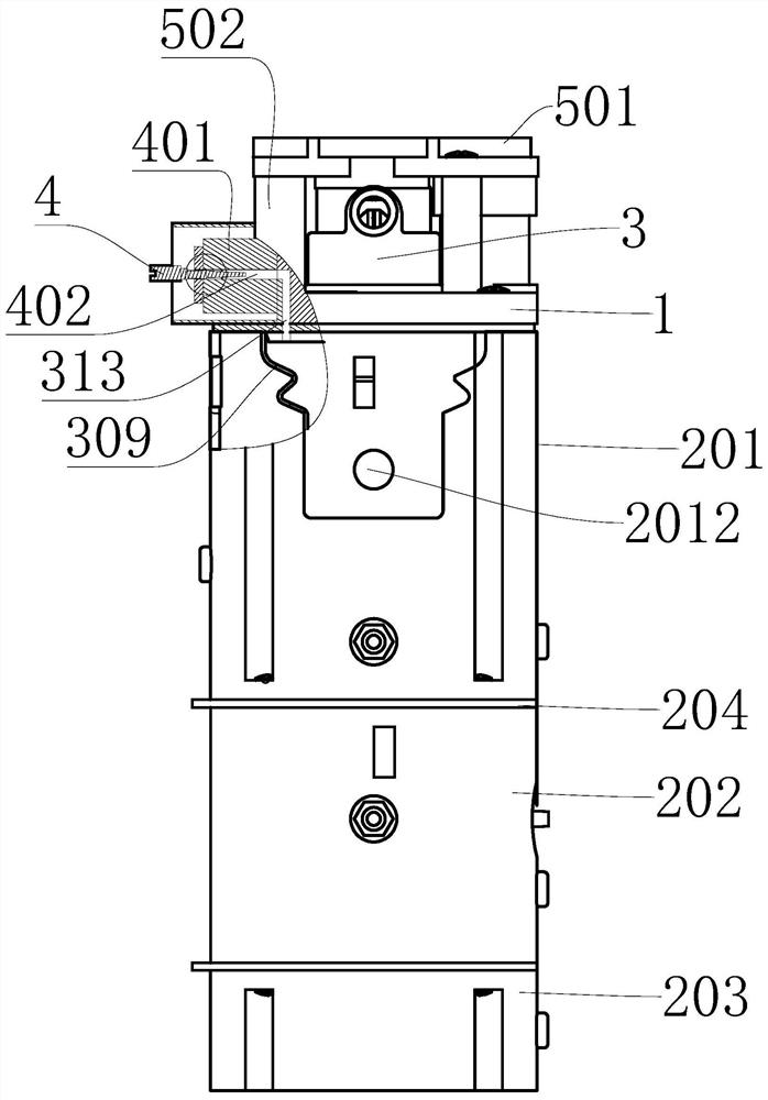
[0025] Such as Figure 1-5 As shown, this embodiment discloses a flushing actuator for a vacuum toilet, including a top cover 1 and an actuator body 2, the top cover 1 is arranged on the actuator body 2, and the feature is that the top cover 1 is provided with a water valve assembly 3, the water valve assembly 3 includes a valve body 301 arranged on the side of the top cover 1 away from the actuator body 2, the valve body 301 is symmetrically provided with a water inlet 302 and a water outlet 303, A water pipe 304 is provided between the water inlet 302 and the water outlet 303, and the valve body 1 is also provided with a first valve stem 305 that passes through the top cover 1 and is exposed in the actuator body 2. The valve stem 305 is provided with an installation chamber 306 communicating with the water passage 304, and the installation chamber 306 is e...


PUM


Abstract

A flushing executing mechanism for a vacuum closestool is disclosed by the invention. The flushing executing mechanism is characterized in that the mechanism includes a top cover and an executing mechanism body, a water valve assembly is arranged on the top cover and comprises a valve body, a water inlet and a water outlet are formed in the valve body, a water pipeline is arranged between the water inlet and the water outlet, and a first valve rod is further arranged on the valve body; the first valve rod is provided with a mounting cavity inside, a second valve rod is arranged in the mounting cavity, and a valve head matched with the sealing water pipeline is arranged on the second valve rod; the top cover is further provided with a corrugated rubber film located in the executing mechanism body, a vacuum cavity is formed between the corrugated rubber film and the top cover, the second valve rod is sleeved with a first spring, the corrugated rubber film is sleeved with a driving block for controlling the second valve rod to slide up and down in a sealed mode, and an air channel communicated with the vacuum cavity is formed in the top cover. Through the arrangement, the executing mechanism body is connected with the water valve assembly, the executing mechanism can also achieve the function of a water inlet valve, the occupied space of the whole equipment is reduced, and the application range of the executing mechanism is wider.

Description

technical field [0001] The invention relates to the technical field of vacuum toilets, in particular to a flushing actuator for vacuum toilets. Background technique [0002] The vacuum toilet is to create a vacuum in the whole system. The system must have an isolation valve to isolate the system from each toilet. When the toilet is flushed, the valve is opened, and the contents of the toilet are taken away by the pressure difference with the atmospheric pressure. Ordinary toilets consume 6 liters of water for one flush, but vacuum toilets only need 0.6 liters; it can also separate urine and feces, and the stool can be directly sent to the fertilizer factory to make organic fertilizer. The vacuum system is maintained by the automatic operation of the vacuum pump. Generally, the vacuum toilet is formed by the vacuum pump and the actuator to form a pressure difference with the atmospheric pressure to take away the contents of the toilet. At the same time, the actuator will cont...

Claims


Application Information

Patent Timeline
Patent Type & Authority Applications(China)
IPC IPC(8): E03D11/02E03D11/13E03D1/36E03D3/10B63B29/14
CPCE03D11/02E03D11/13E03D1/36E03D3/10B63B29/14
Inventor 潘建光
Owner ZHEJIANG JIANJIANG SHIP TECH CO LTD
Why Eureka
Try Eureka