Drying device for grain production and working method thereof

A drying device and grain technology, applied in drying, drying machines, heating devices, etc., can solve the problems of low drying efficiency, inability to dry grain, inconvenient filtration of dust or weeds, etc., and increase the heating area , Improve drying efficiency and reduce damage

Pending Publication Date: 2021-12-31
凤台县淮之苗农业发展有限公司
View PDF9 Cites 0 Cited by
  • Summary
  • Abstract
  • Description
  • Claims
  • Application Information

AI Technical Summary

Problems solved by technology

[0003] Before the grain on the market is produced and processed, the grain itself is in a wet state. Drying by sunlight is easily affected by weather factors, which reduces the efficiency of grain production. It is necessary to dry the grain through drying equipment, but the traditional drying The drying efficiency of the equipment is low, and the grain cannot be dried effectively. At the same time, when the drying operation is performed, there will be a small amount of dust or weeds in the dried grain, which is inconvenient to filter out

Method used


Image

  • Drying device for grain production and working method thereof
  • Drying device for grain production and working method thereof
  • Drying device for grain production and working method thereof

Examples


Embodiment 1

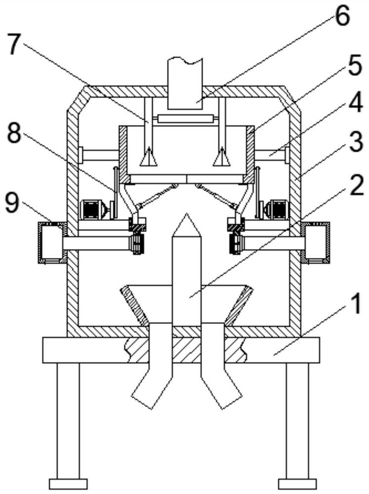
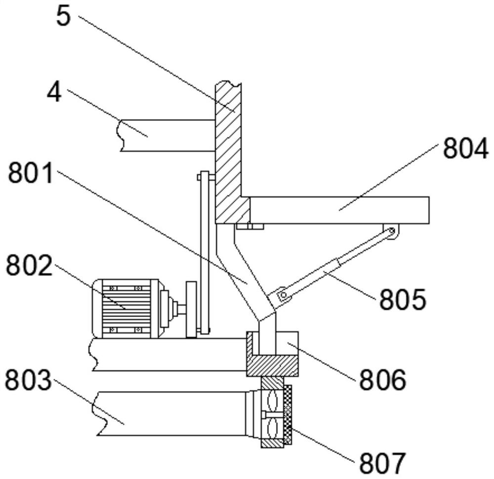
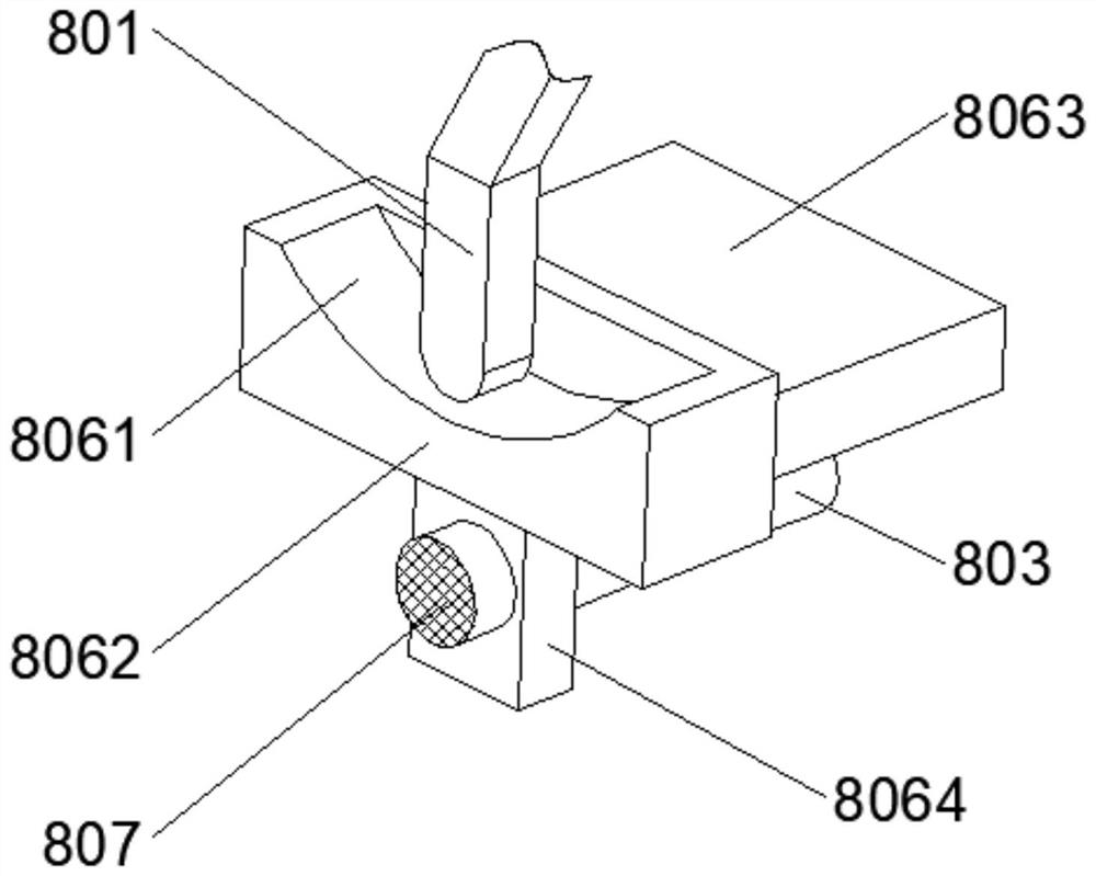
[0034] see figure 2As shown, the above-mentioned rocking mechanism 8 includes a support frame 801 fixedly connected to the bottom of the storage box 5. The middle part of the support frame 801 is hinged with an electric push rod 805. The bottom surface of the storage box 5 is provided with a discharge hole. The extension of the electric push rod 805 The outlet is hinged with a door 804, and one end of the door 804 is hinged with the storage box 5, and the door 804 is opened or closed by an electric push rod 805, so that it is convenient to control the grain for the next production and processing process and reduce labor costs. In the process of operation, the two sides of the storage box 5 are fixedly connected with the rotating shaft 4, and the two rotating shafts 4 are connected to the shell 3 through bearings, and the storage box 5 is conveniently limited by the rotating shaft 4 to prevent the storage box 5 from falling. In this case, the bottom of the support frame 801 is...

Embodiment 2

[0039] see Figure 5 As shown, the above-mentioned drying mechanism 7 includes two first fixed rods 702 that are fixedly connected to the top of the inner wall of the housing 3, and the bottom ends of the two first fixed rods 702 are fixedly equipped with a partition block 703, and the two first fixed rods The middle part of 702 is fixedly connected with a mounting plate 705, and the two mounting plates 705 are fixedly connected by several electric heating rods 701, and the food in the storage box 5 is separated and mixed through the partition block 703, and then passed through several electric heating rods. 701 to dry it efficiently, one end of the two mounting plates 705 is fixedly connected with a second fixed rod 704, and the tops of the two second fixed rods 704 are fixedly connected with the top of the inner wall of the shell 3, and several electric heating rods 701 A feeding pipe 6 is arranged above the top of the feeding pipe 6 , and the top end of the feeding pipe 6 r...


PUM


Abstract

The invention relates to a drying device for grain production and a working method thereof.The drying device comprises a base, a shell is fixedly installed at the top of the base, a cavity is formed in the shell, a storage box used for loading grains is arranged in the middle of the cavity, and a drying mechanism used for drying the grains is arranged above the storage box; shaking mechanisms are arranged on the two sides of the bottom of the storage box, a separation mechanism is arranged below the storage box, recovery mechanisms used for recovering weeds are arranged on the outer walls of the two sides of the shell, the storage box swings through operation of a driving motor, and grains in the storage box are mixed in cooperation with a separation block; and the grain drying efficiency is improved, an electric push rod controls an opening and closing door, grain feeding is conveniently controlled, dust and weeds in grains are absorbed in cooperation with a draught fan and a filter screen, meanwhile, airflow driven by the draught fan also takes away residual damp heat on the surfaces of the grains, and the situation that the grains are damaged is reduced.

Description

technical field [0001] The invention relates to the technical field of grain production, in particular to a drying device for grain production and a working method thereof. Background technique [0002] Grain production refers to a certain area in a certain period of time. Under certain economic and technological conditions, it is formed by the comprehensive input of various production factors and can stably achieve a certain amount of grain output; including cultivated land protection capabilities, production technology levels, and policy guarantees. capabilities, scientific and technological service capabilities, and natural disaster resilience. [0003] Before the grain on the market is produced and processed, the grain itself is in a wet state. Drying by sunlight is easily affected by weather factors, which reduces the efficiency of grain production. It is necessary to dry the grain through drying equipment, but the traditional drying The drying efficiency of the equipm...

Claims


Application Information

Patent Timeline
Patent Type & Authority Applications(China)
IPC IPC(8): F26B9/06F26B23/04F26B25/00F26B25/12
CPCF26B9/063F26B23/04F26B25/002F26B25/12
Inventor 陈运陈传安童晓红关立松王立涛王树飞高矿
Owner 凤台县淮之苗农业发展有限公司
Why Eureka
Try Eureka