Air energy heat pump dryer

An air energy heat pump and dryer technology, which is applied in the direction of dryers, drying, pumps, etc., can solve problems such as easy dust accumulation and blockage

Inactive Publication Date: 2021-12-31
广东碧朗节能设备有限公司
View PDF3 Cites 0 Cited by
  • Summary
  • Abstract
  • Description
  • Claims
  • Application Information

AI Technical Summary

Problems solved by technology

[0005] Aiming at the deficiencies of the prior art, the present invention provides an air energy heat pump dryer, which solves the problem that the inside of the traditional air energy heat pump dryer is easy to accumulate dust and block

Method used


Image

  • Air energy heat pump dryer
  • Air energy heat pump dryer
  • Air energy heat pump dryer

Examples


Embodiment Construction

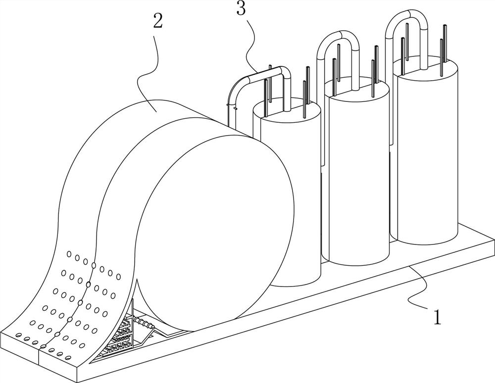
[0027] use Figure 1-Figure 7 An air energy heat pump dryer according to an embodiment of the present invention is described as follows.

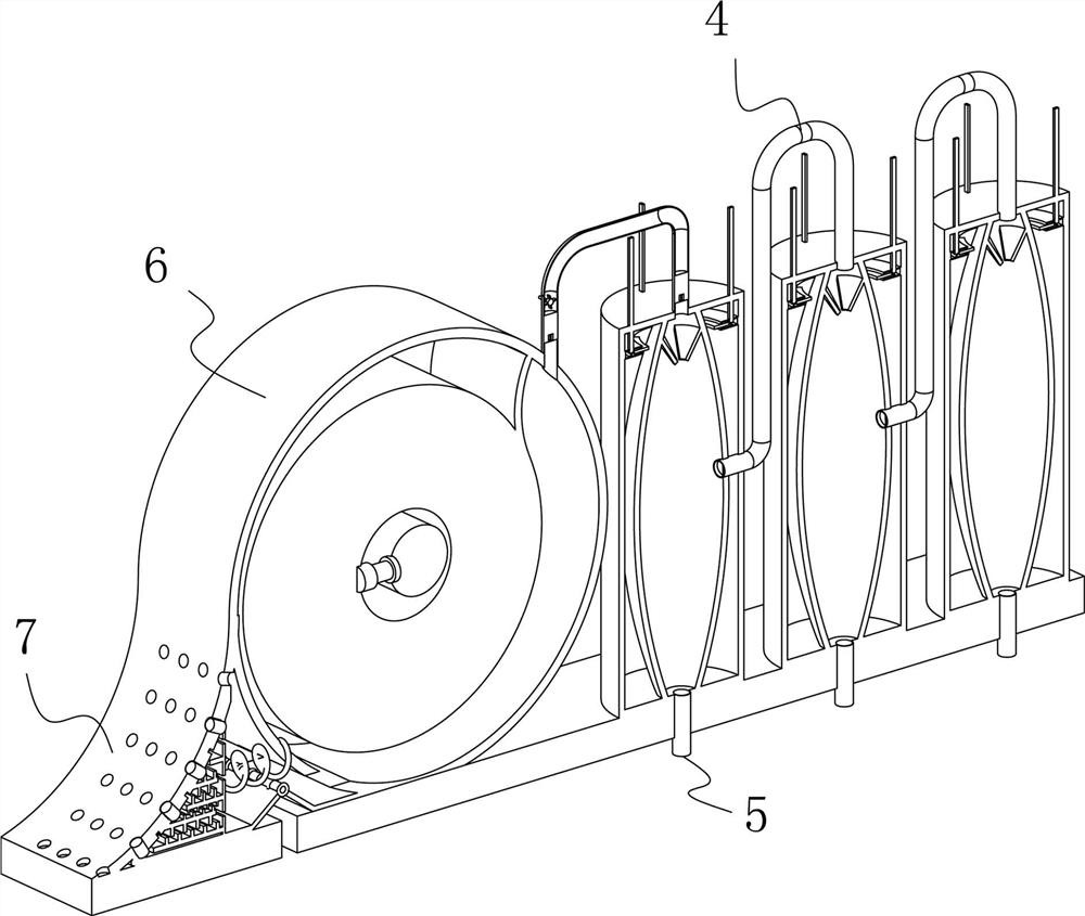
[0028] Such as Figure 1-Figure 7 As shown, an air energy heat pump dryer according to the present invention includes a bottom plate 1; The lower surface of the mechanism 3 is linearly arranged along the upper surface of the bottom plate 1, the outer surface of the booster mechanism 3 is fixedly connected with a connecting pipe 4, and the bottom of the connecting pipe 4 is provided with a pressure relief valve 5, which is located in the suction mechanism 2, the suction mechanism 2 includes a compression mechanism 6, and the left side of the compression mechanism 6 is provided with a dustproof mechanism 7.

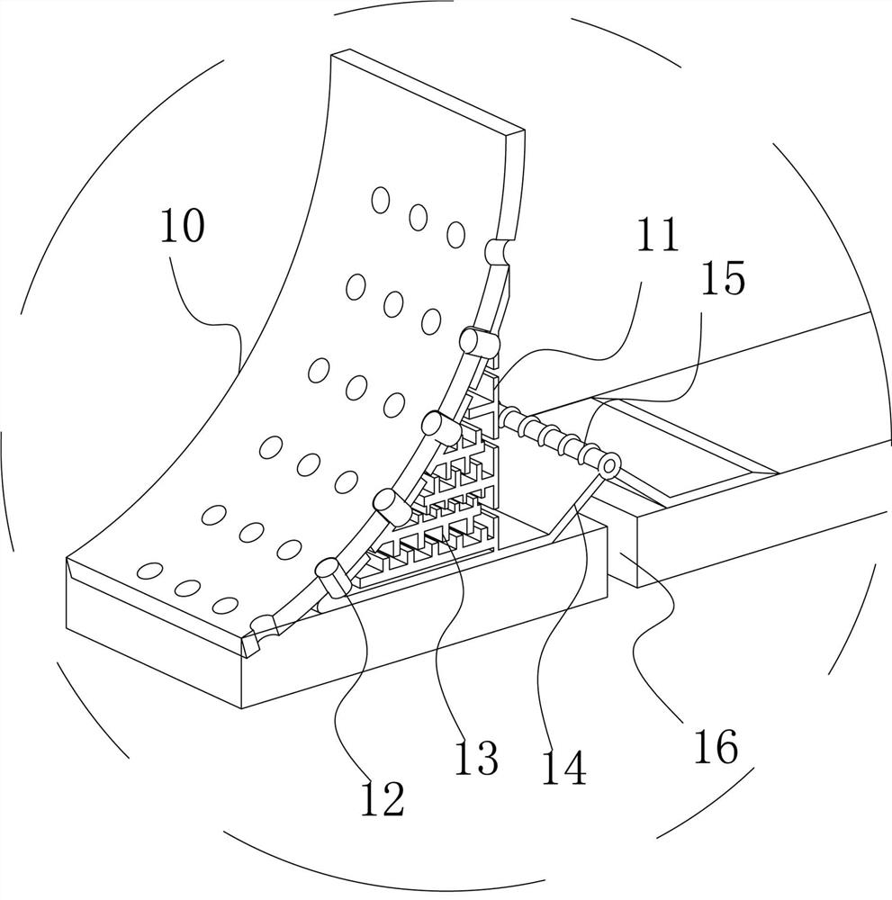
[0029] The dustproof mechanism 7 includes a leaking plate 10, the lower surface of the leaking plate 10 is fixedly connected with the upper surface of the bottom plate 1, the right side of the leaking plate 10 is movably connected with...


PUM


Abstract

The invention belongs to the field of dryers, and particularly relates to an air energy heat pump dryer, which comprises a bottom plate; and an air suction mechanism is fixedly connected to the upper surface of the bottom plate, a pressurizing mechanism is arranged on the right side of the air suction mechanism, and the lower surface of the pressurizing mechanism is linearly arranged along the upper surface of the bottom plate. According to the air energy heat pump dryer provided by the invention, a control mechanism and a check plate are arranged, when air enters the dryer, under the influence of the air pressure difference, a fixed block is separated from a conical block, high-pressure airflow blows a turbine to rotate, and flow information is displayed to the outside through rotation of the internal turbine, when the supercharging mechanism leaks, the sealing performance of the supercharging mechanism is reduced, and the air flow flows back in the opposite direction; in order to reduce the impact of the water hammer effect on a pipeline, the check plate and the conical block can be reversely closed under the action of the air flow, all air storage bottles are prevented from being damaged by chain reaction, the impact force and the pressure are released by sacrificing a single air storage bottle, and the problems that traditional high-pressure air flow flows back, the pressure cannot be leaked, and the interior of equipment is prone to being damaged are solved.

Description

technical field [0001] The invention belongs to the field of dryers, in particular to an air energy heat pump dryer. Background technique [0002] The air energy heat pump dryer uses the reverse Carnot principle. The gas Freon is pressurized by the compressor to become a high-temperature and high-pressure gas (temperature up to 100°C), which enters the heat exchanger (condenser) on the indoor side, and the refrigerant condenses and liquefies to release high temperature. A device that heats and dries the air in a room. [0003] The traditional air energy heat pump dryer needs to absorb a large amount of air from the outside when it is in use. For areas with serious pollution, there are many particles in the air. After the equipment works for a long time, a large amount of dust will accumulate inside, which will seriously block the air. Inside the device, affecting the normal use of the device. Contents of the invention [0004] (1) Solved technical problems [0005] Aimi...

Claims


Application Information

Patent Timeline
Patent Type & Authority Applications(China)
IPC IPC(8): F26B21/00F04B35/01F04B41/02
CPCF26B21/001F26B21/003F26B21/004F04B35/01F04B41/02
Inventor 徐枝泉
Owner 广东碧朗节能设备有限公司
Why Eureka
Try Eureka