Drilling and sampling equipment for engineering detection

A sampling equipment and engineering detection technology, applied in the direction of sampling devices, etc., can solve the problems of unsuitable concrete sampling, damage to the original state of concrete, inconvenient detection and other tests, and achieve simple and efficient sampling operation, convenient and fast separation, and well-preserved shape Effect

Inactive Publication Date: 2021-12-31
SICHUAN UNIV
View PDF7 Cites 2 Cited by
  • Summary
  • Abstract
  • Description
  • Claims
  • Application Information

AI Technical Summary

Problems solved by technology

[0004] The sampling device in the prior art has the following disadvantages: the sampling device is not suitable for sampling concrete, and the concrete blocks after sampling are fragmented, which is not convenient for subsequent tests such as detection, and the sampling device destroys the original state of the concrete. Therefore, the present invention A kind of borehole sampling equipment for engineering testing is proposed here

Method used


Image

  • Drilling and sampling equipment for engineering detection
  • Drilling and sampling equipment for engineering detection
  • Drilling and sampling equipment for engineering detection

Examples


Embodiment 1

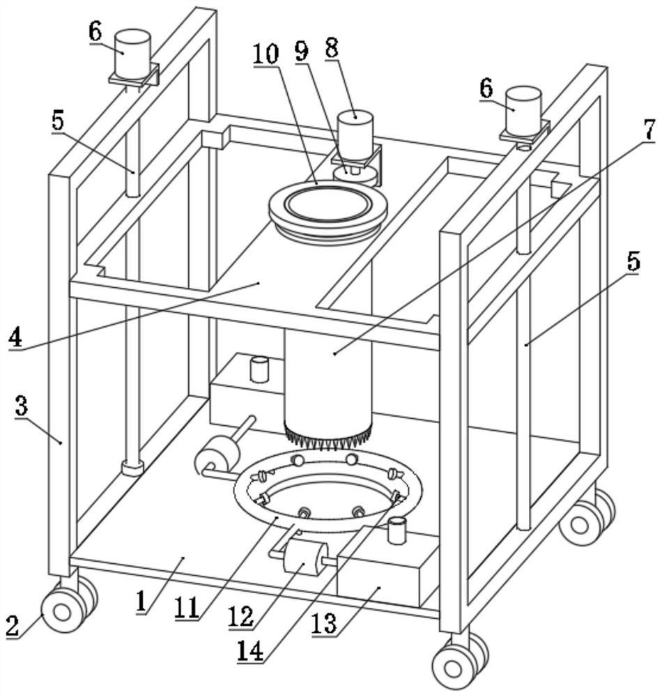
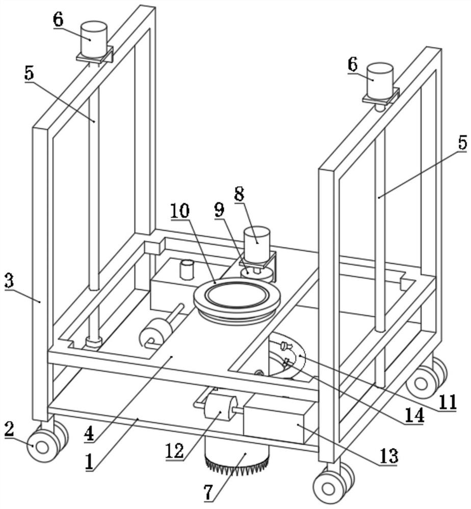
[0031] refer to Figure 1-3 , a drilling sampling device for engineering testing, comprising a base 1, a stand 3 is symmetrically installed on the upper side of the base 1, a plurality of universal wheels 2 are installed on the lower side of the base 1, and a lifting plate is provided on the upper side of the base 1 4. The two ends of the lifting plate 4 are slidingly installed with the stand 3 respectively, and the stand 3 is rotated and installed with a lifting screw 5, which is threadedly installed with the lifting plate 4, and the lifting screw 5 is driven by the lifting motor 6, and the lifting Screw mandrel 5 is two, and two lifting screw mandrels 5 are threadedly installed with the two ends of lifting plate 4 respectively, and two lifting screw mandrels 5 are driven by lifting motor 6 respectively.

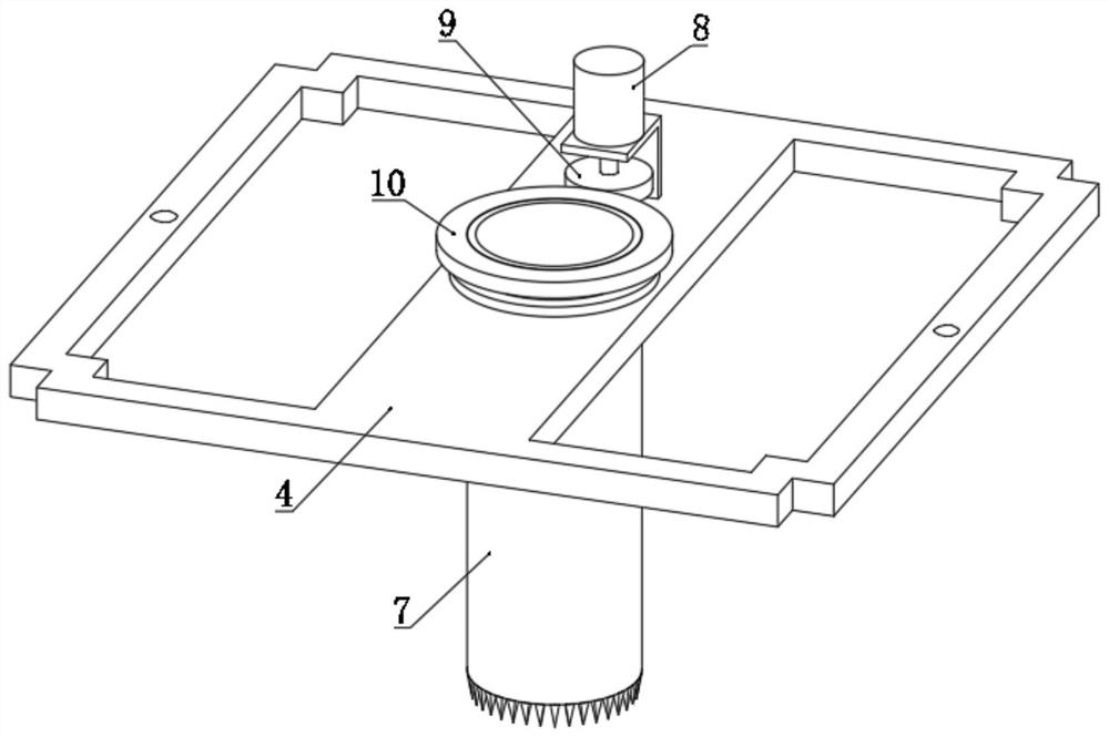
[0032] The lifting plate 4 is rotated and installed with a sampling drum 7. The sampling drum 7 is driven by a drive motor 8. The bottom of the sampling drum 7 is provided ...

Embodiment 2

[0040] refer to Figure 4-6 , present embodiment 2 is on the basis of above-mentioned embodiment 1, offers threaded hole in the inside of one side of sampling drum 7, and is installed with clamping screw rod 15 through threaded hole thread, the inner wall of sampling drum 7 and is positioned at threaded hole. One side of the bottom of the hole is provided with a slotted hole 16, and the bottom end of the clamping screw rod 15 extends into the slotted hole 16, and the side of the slotted hole 16 near the center of the sampling drum 7 is rotated by a rotating shaft 18 to install a clamping block 17, the clamping block One side of 17 is in frictional contact with the bottom end of the clamping screw rod 15 .

[0041] Such as Figure 5 As shown in , two limit rings 20 are symmetrically installed on the outside of the top of the sampling drum 7 , and the two limit rings 20 are slidably attached to the top surface and the bottom surface of the lifting plate 4 respectively.

[0042] ...


PUM


Abstract

The invention discloses drilling and sampling equipment for engineering detection, and belongs to the field of engineering sampling. The drilling and sampling equipment comprises a base, vertical frames are symmetrically mounted on the upper side of the base, a plurality of universal wheels are mounted on the lower side of the base, a lifting plate is arranged on the upper side of the base, the two ends of the lifting plate are slidably mounted on the vertical frames respectively, the vertical frames are rotatably provided with lifting screw rods, the lifting screw rods and the lifting plate are in threaded installation, the lifting screw rods are driven by a lifting motor, the lifting plate is rotatably provided with a sampling rotary drum, the sampling rotary drum is driven by a driving motor, and the bottom end of the sampling rotary drum is provided with a plurality of crushing cones. According to the device, local sampling operation can be carried out on a concrete slab, the sampled sample is cylindrical, the shape is well preserved, the sampling process is simple, an acetone solution is sprayed during sampling, and a protective film can be formed after the acetone solution is dried so that the physical and chemical properties of the sample are prevented from being damaged due to the influence of the external environment.

Description

technical field [0001] The invention relates to the technical field of engineering sampling, in particular to a drilling sampling device for engineering testing. Background technique [0002] During the construction process of the project, it is necessary to take partial sampling of the concrete slab and test the taken concrete samples, including analyzing the physical and chemical properties of its main components, performing hardness tests, tensile tests and other mechanical performance tests on them. [0003] After retrieval, Chinese Patent No. CN 214309634 U discloses a drilling sampling device for engineering material detection, which includes a sampling column, and a sampling cavity is provided at the lower end of the sampling column, and it is characterized in that: the sampling cavity is along the axial direction of the sampling column There is a blocking plate slidingly connected with the outer wall of the sampling column along the axial direction of the sampling co...

Claims


Application Information

Patent Timeline
Patent Type & Authority Applications(China)
IPC IPC(8): G01N1/08
CPCG01N1/08
Inventor 刘文睿白诗艺
Owner SICHUAN UNIV
Why Eureka
Try Eureka