Lamp bead module, backlight module and electronic equipment

A backlight module and module technology, applied in the direction of circuits, electrical components, semiconductor devices, etc., can solve the problems of unfavorable light and thin design of electronic equipment, small light mixing distance, and impossibility of realization, so as to achieve light and thin design, low mixing The effect of increasing the light distance and increasing the divergence angle

Active Publication Date: 2021-12-31
江西省兆驰光电有限公司
View PDF19 Cites 0 Cited by
  • Summary
  • Abstract
  • Description
  • Claims
  • Application Information

AI Technical Summary

Problems solved by technology

[0004] Aiming at the deficiencies of the prior art, the object of the present invention is to provide a lamp bead module, a backlight module and electronic equipment, aiming to solve the problem that in the prior art, the design of the optical lens occupies the space between the LED lamp bead and the diffusion plate in the backlight module. The gap between them cannot achieve a smaller light mixing distance, which is not conducive to the technical problem of thin and light design of electronic equipment

Method used


Image

  • Lamp bead module, backlight module and electronic equipment
  • Lamp bead module, backlight module and electronic equipment
  • Lamp bead module, backlight module and electronic equipment

Examples


Embodiment Construction

[0020] In order to facilitate the understanding of the present invention, the present invention will be described more fully below with reference to the associated drawings. Several embodiments of the invention are shown in the drawings. However, the present invention can be embodied in many different forms and is not limited to the embodiments described herein. Rather, these embodiments are provided so that the disclosure of the present invention will be thorough and complete.

[0021] It should be noted that when an element is referred to as being “fixed on” another element, it may be directly on the other element or there may be an intervening element. When an element is referred to as being "connected to" another element, it can be directly connected to the other element or intervening elements may also be present. The terms "vertical," "horizontal," "left," "right," and similar expressions are used herein for purposes of illustration only.

[0022] Unless otherwise def...


PUM


Abstract

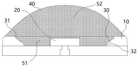
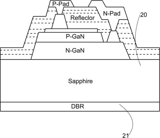
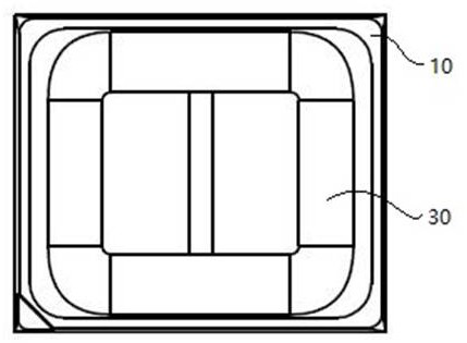
The invention provides a lamp bead module, a backlight module and electronic equipment, the lamp bead module comprises a support and a bowl cup arranged in the support, a wafer is arranged in the bowl cup, the bowl cup is filled with a first packaging adhesive, the first packaging adhesive covers the wafer, one side of the first packaging adhesive is provided with a second packaging adhesive, and the second packaging adhesive is in a convex lens shape. The second packaging adhesive is arranged on the light emitting side of the wafer, the second packaging adhesive is arranged on the side, away from the wafer, of the first packaging adhesive, a step groove is formed in the edge of the side, away from the wafer, of the bowl cup, and the second packaging adhesive covers the step groove. According to the lamp bead module, the bowl cup is filled with the first packaging adhesive, and the convex-lens-shaped second packaging adhesive is further arranged on the outer side of the first packaging adhesive; specifically, the second packaging adhesive is arranged to form the ball head to replace an optical lens in the prior art, the limitation of the thickness of the secondary optical lens is removed, so that the low light mixing distance is achieved; and the light and thin design of the product is facilitated.

Description

technical field [0001] The invention relates to the technical field of LEDs, in particular to a lamp bead module, a backlight module and electronic equipment. Background technique [0002] With the improvement of people's living standards, people gradually tend to pursue thinner and more beautiful designs when choosing electronic devices such as televisions. [0003] In the prior art, the LED lamp beads in the backlight module of the TV set need to be equipped with a lens to realize the refraction and diffusion of light, so that the point light source of the LED lamp beads forms a surface light source, which is irradiated on the diffusion plate and released on the screen. This optical lens design occupies the gap between the LED lamp bead and the diffusion plate in the backlight module, and cannot achieve a smaller light mixing distance, which is not conducive to the thin and light design of electronic equipment. Contents of the invention [0004] Aiming at the deficienci...

Claims


Application Information

Patent Timeline
Patent Type & Authority Applications(China)
IPC IPC(8): H01L33/48H01L33/58H01L33/60H01L33/54
CPCH01L33/486H01L33/58H01L33/60H01L33/54
Inventor 卢鹏王金鑫程杰东
Owner 江西省兆驰光电有限公司
Why Eureka
Try Eureka