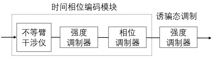
Time phase encoding device and quantum key distribution system
An encoding device and time phase technology, applied to key distribution, can solve problems such as increasing system complexity and sensitivity to the ambient temperature of the intensity modulator, and achieve the effect of improving stability and practicability, and consistent loss
- Summary
- Abstract
- Description
- Claims
- Application Information
AI Technical Summary
Problems solved by technology
Method used
Image

Examples
Embodiment 1
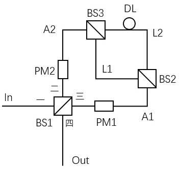
[0041] The structure of the time-phase encoding device is: the unequal arm interferometer includes a second beam splitter BS2, a third beam splitter BS3 and an optical fiber delay line DL, and the second beam splitter BS2 and the third beam splitter Beamer BS3 is connected by optical fibers L1 and L2 to form an unequal-arm Mach-Zehnder interferometer. The optical fiber L1 is the short arm of the Mach-Zehnder interferometer. The optical fiber delay line DL is located on the optical fiber L2 as a Mach-Zehnder interferometer. - the long arm of the Zehnder interferometer, the second beam splitter BS2 and the third beam splitter BS3 are connected to the optical fiber A1 and the optical fiber A2 respectively, and the unequal-arm Mach-Zehnder interferometer is used to split the input light The pulse is divided into front and rear sub-pulses with time difference and same polarization.
[0042] Embodiment 1 The time phase encoding process includes:
[0043] The horizontally polarized ...
Embodiment 2
[0048] The structure of the time-phase encoding device is: the optical fiber at the first port of the first beam splitter BS1 is fused at 45°, and the unequal arm interferometer includes a first polarization beam splitter PBS1, a first Faraday reflector mirror FM1 and the second Faraday mirror FM2, the first port and the third port of the first polarization beam splitter PBS1 are respectively connected to the optical fiber A1 and the optical fiber A2, and the second port and the fourth port are respectively connected to the optical fiber L3 and the optical fiber L4 Connected with the first Faraday mirror FM1 and the second Faraday mirror FM2, the unequal-arm interferometer is used to divide the input optical pulse into front and rear sub-pulses with time difference and polarization perpendicular to each other, the first phase modulator PM1 and the second phase modulator PM2 support dual polarization operation.
[0049] Embodiment 2 The time phase encoding process includes:
...
Embodiment 3
[0055] The structure of the time phase encoding device is: the optical fiber at the first port of the first beam splitter BS1 is fused at 45°, the unequal arm interferometer includes a second polarization beam splitter PBS2, and the second The first port and the third port of the polarization beam splitter PBS2 are respectively connected with the optical fiber A1 and the optical fiber A2, and the second port and the fourth port are directly connected through the optical fiber L5, and the unequal arm interferometer is used to divide the input optical pulse into The first phase modulator PM1 and the second phase modulator PM2 support dual-polarization operation with a time difference between the front and rear sub-pulses and the polarizations are perpendicular to each other.
[0056] Embodiment 3 The time phase encoding process includes:
[0057] The horizontally polarized optical pulse P0 enters the time-phase encoding device from the input port In, first the polarization state...
PUM
 Abstract
Description
Claims
Application Information
 - Generate Ideas
- Intellectual Property
- Life Sciences
- Materials
- Tech Scout
- Unparalleled Data Quality
- Higher Quality Content
- 60% Fewer Hallucinations
Browse by: Latest US Patents, China's latest patents, Technical Efficacy Thesaurus, Application Domain, Technology Topic, Popular Technical Reports.
© 2025 PatSnap. All rights reserved.Legal|Privacy policy|Modern Slavery Act Transparency Statement|Sitemap|About US| Contact US: help@patsnap.com