
Box-type liquid cooling equipment for data center

A data center, liquid cooling technology, applied in electrical equipment structural parts, cooling/ventilation/heating renovation, electrical components, etc., can solve the problem that liquid cooling equipment does not have the function of synchronous control of liquid transportation and equal transmission, and does not have heat exchange. Fast and continuous heat dissipation of parts, lack of self-locking auxiliary components, etc., to achieve the effect of reducing temperature, accurately positioning heat dissipation function, and ensuring continuity

Inactive Publication Date: 2021-12-31
陈丽群
View PDF1 Cites 0 Cited by
  • Summary
  • Abstract
  • Description
  • Claims
  • Application Information

AI Technical Summary

Problems solved by technology

[0008] The purpose of the present invention is to provide a box-type liquid cooling equipment for data centers to solve the first problem mentioned in the above background technology. The current liquid cooling equipment does not have the equal transmission function of synchronously controlling the liquid delivery of both sides of the heat exchange, and cannot continue Rapid cooling of the cooling oil; second, there is no rapid and continuous cooling of the heat exchange parts, and a flow guide structure to ensure continuous and uniform heat exchange when the gas flows; third, there is no self-locking auxiliary component that is convenient for sealing the top

Method used


Image

  • Box-type liquid cooling equipment for data center
  • Box-type liquid cooling equipment for data center
  • Box-type liquid cooling equipment for data center

Examples


Embodiment Construction

[0034] The following will clearly and completely describe the technical solutions in the embodiments of the present invention with reference to the accompanying drawings in the embodiments of the present invention. Obviously, the described embodiments are only some, not all, embodiments of the present invention.

[0035] In the description of the present invention, unless otherwise stated, the meaning of "plurality" is two or more; the terms "upper", "lower", "left", "right", "inner", "outer" , "front end", "rear end", "head", "tail", etc. indicate the orientation or positional relationship based on the orientation or positional relationship shown in the drawings, and are only for the convenience of describing the present invention and simplifying the description, rather than Nothing indicating or implying that a referenced device or element must have a particular orientation, be constructed, and operate in a particular orientation should therefore not be construed as limiting ...


PUM


Abstract

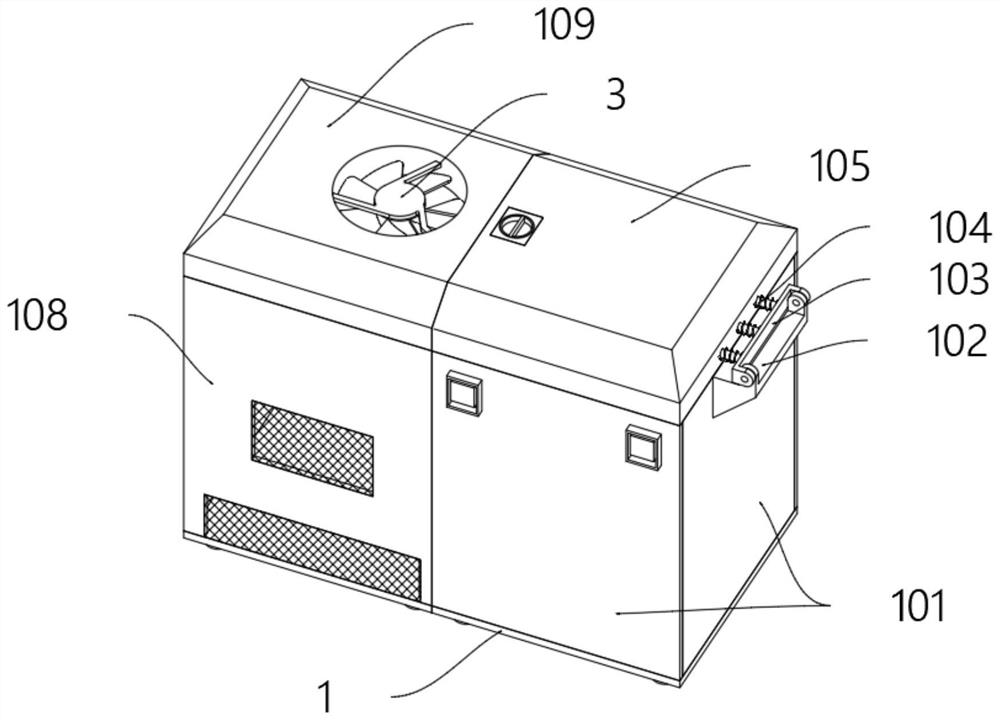
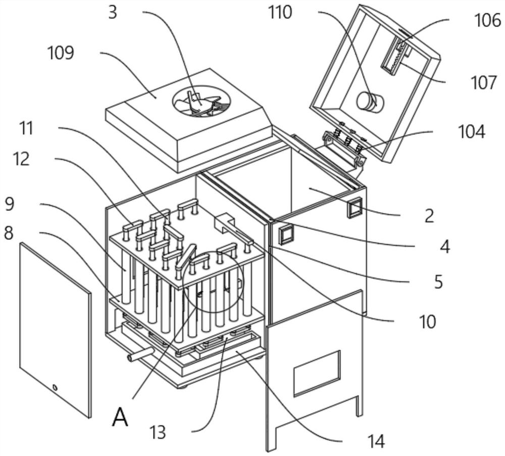
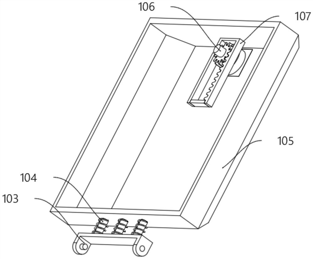
The invention discloses box-type liquid cooling equipment for a data center, relates to the technical field of cooling, and solves the problems that currently used liquid cooling equipment does not have an equivalent transmission function of synchronously controlling liquid conveying of two heat exchange parties and cannot continuously and quickly cool cooling oil. The data center box-type liquid cooling equipment comprises a bottom plate, three groups of front bin plates are fixedly arranged on the front side of the top of the bottom plate, a rotating frame is fixedly arranged on the top of the front side of each front bin plate, and a shaft frame is rotationally arranged on the front side of each rotating frame through hinge connection. and by arranging a twelve-bladeimpeller, hydraulic oil is driven to be conveyed in the rotating process of the twelve-blade impeller, a spring column can guarantee that the sides of elastic push blocks are attached to the inner wall of a one-way channel, when the elastic push blocks are attached to the inclined face of the inner side of the one-way channel, the elastic push blocks are automatically contracted, the space between the two sets of elastic push blocks is reduced, the hydraulic oil is discharged from the bottom of the one-way channel, and cooling oil can be cooled continuously and rapidly.

Description

technical field [0001] The invention relates to the technical field of cooling and cooling, in particular to a data center box-type liquid cooling device. Background technique [0002] The cooling conduction of the liquid is better, and the oil has insulating properties, so the cooling oil is generally used to cool the data chassis, which will not affect the normal power supply of the line. [0003] After searching, for example, the patent with the publication number CN206061395U discloses a box-type liquid-cooled radiator, including a lower shell and an upper cover, a seal is provided on the top of the lower shell, and a water nozzle is also provided on the side wall of the lower shell. A connector, the nozzle connector communicates with the flow channel. The utility model adopts the low-temperature liquid flowing in the flow channel to dissipate heat from the heat-generating components in the lower casing. This liquid-cooled heat-dissipating mode can rapidly and effective...

Claims


Application Information

Patent Timeline
Patent Type & Authority Applications(China)
IPC IPC(8): H05K7/20
CPCH05K7/208H05K7/20718
Inventor 陈丽群
Owner 陈丽群
Learn More