Engine guide vane wax pattern placing device
A guide vane and engine technology, applied in the field of investment precision casting, can solve the problems affecting the precision and quality of engine guide vane processing, softening and deformation of the surface of the wax mold, and affecting the qualified rate of the engine, so as to avoid softening and deformation and improve reliability , Guarantee the effect of precise shape
- Summary
- Abstract
- Description
- Claims
- Application Information
AI Technical Summary
Problems solved by technology
Method used
Image

Examples
Embodiment Construction
[0025] The technical solutions in the embodiments of the present invention will be clearly and completely described below. Obviously, the described embodiments are only some of the embodiments of the present invention, but not all of them. Based on the embodiments of the present invention, all other embodiments obtained by persons of ordinary skill in the art without making creative efforts belong to the protection scope of the present invention.
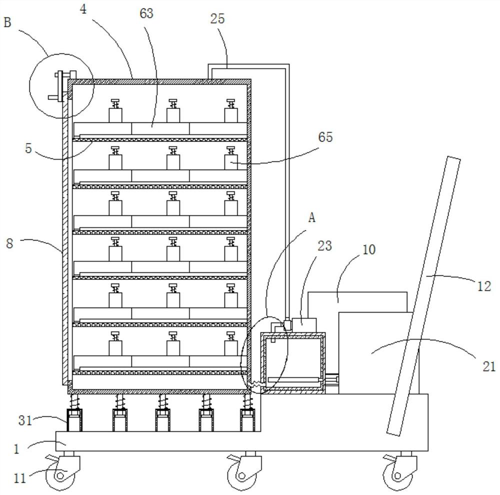
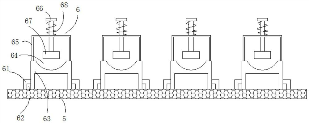
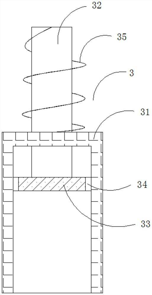
[0026] see Figure 1-5 , a device for placing a wax mold of an engine guide vane, comprising a base 1, a refrigeration mechanism 2 and a plurality of buffer mechanisms 3 fixedly connected to the upper surface of the base 1, a placement box 4 fixedly connected to the top of the plurality of buffer mechanisms 3, and a placement box 4 The inner wall of the inner wall is fixedly connected with a plurality of supporting net plates 5, and the upper surface of the supporting net plates 5 is fixedly connected with a plurality of sets of pla...
PUM
 Abstract
Description
Claims
Application Information
PatSnap Eureka turns technology decisions into work you can execute. Powered by our Innovation Knowledge Graph, it runs expert workflows across engineering, life sciences, materials and intellectual property. Get your review-ready output in minutes.


