Supercharge Your Innovation With Domain-Expert AI Agents!

Critical patient craniocerebral monitor device for intensive care medicine

A technology for critically ill patients and monitoring devices, applied in the field of medical devices to achieve the effect of increasing the degree of fit

Inactive Publication Date: 2022-01-07
达州市中心医院
View PDF0 Cites 0 Cited by
  • Summary
  • Abstract
  • Description
  • Claims
  • Application Information

AI Technical Summary

Problems solved by technology

[0005] In order to solve the above technical problems, the present invention provides a cranial monitoring device for critically ill patients used in intensive care medicine to solve existing problems

Method used


Image

  • Critical patient craniocerebral monitor device for intensive care medicine
  • Critical patient craniocerebral monitor device for intensive care medicine
  • Critical patient craniocerebral monitor device for intensive care medicine

Examples


Embodiment 1

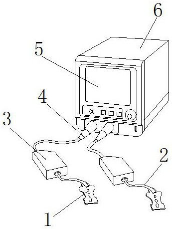
[0031] as attached figure 1 to attach Figure 6 Shown:

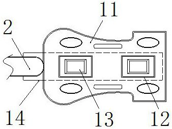
[0032]The present invention provides a craniocerebral monitoring device for critically ill patients, the structure of which includes an induction sheet 1, a conductive wire 2, an integrator 3, a transmission wire 4, a display screen 5, and a host 6. The upper end of the induction sheet 1 is connected to the The lower end of the conductive wire 2 is embedded and connected, the upper end of the conductive wire 2 is embedded and installed on the lower end of the integrator 3, the upper end of the integrated device 3 is embedded and connected to the lower end of the transmission wire 4, and the upper end of the transmission wire 4 is snapped and installed on the host 6 Outside the front end, the inner side of the display screen 5 is embedded and installed on the outer side of the host 6, and the induction sheet 1 includes a main paste board 11, a conductive plate 12, an induction board 13, and a connection plate 14, and th...

Embodiment 2

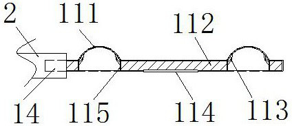
[0040] as attached Figure 7 to attach Figure 9 Shown:

[0041] The present invention provides a craniocerebral monitoring device for critically ill patients. The auxiliary patch 114 includes a reinforcing plate 141, an embedding plate 142, a fitting suction cup 143, and an installation block 144. The outer side of the reinforcing plate 141 is embedded Installed on the inner side of the embedded plate 142, the upper end of the reinforcing plate 141 is embedded and installed on the lower end of the fixed plate 112, the upper end of the embedded plate 142 is embedded and installed on the lower end of the outer pressure plate 122, and the upper end of the fitting suction cup 143 is vertically installed on the mounting plate The lower end of the block 144, the upper end of the installation block 144 is attached to the lower end of the reinforcement plate 141, and the outer side of the installation block 144 is snapped and installed on the inner side of the embedded plate 142. S...


PUM


Abstract

The invention provides a critical patient craniocerebral monitor device for intensive care medicine. The device structurally comprises an induction sheet, a conduction wire, an integrator, a transmission wire, a display screen and a host, wherein the upper end of the induction sheet is fixedly connected with the lower end of the conduction wire; the upper end of the conduction wire is fixedly mounted at the lower end of the integrator; the upper end of the integrator is embedded and fixedly connected with the lower end of the transmission wire; the upper end of the transmission wire is clamped and arranged outside the front end of the host, the inner side of the display screen is fixedly embedded and arranged on the outer side of the host; air in the air pressure wall is extruded by pressing the air pressure wall, and then the main pasting plate is attached to the brain cortex of a patient; after extrusion on the air pressure wall is released, an elastic block and a side-push plate are pressed by an elastic plate, the elastic block and the side-push plate lose extrusion force and deliver the reactive force into the elastic plate, the elastic plate and the air pressure wall are supported through the elasticity of the elastic plate and the air pressure wall, so that the inner side of a fixing wall forms a vacuum state to fix the brain cortical tissue of the patient.

Description

technical field [0001] The invention belongs to the field of medical devices, and more specifically relates to a brain monitoring device for critically ill patients used in intensive care medicine. Background technique [0002] Blood oxygen saturation refers to the degree of oxygen binding of hemoglobin under a certain oxygen partial pressure. Usually, arterial blood oxygen saturation is used, and blood oxygen saturation monitors are required for the treatment and monitoring of some critically ill patients. For real-time monitoring, the red light and infrared light emitted by the light-emitting diode in the sensor sheet penetrate the peripheral tissue of the human body, and the light absorption rate of the pulsating money in the blood vessel and after the pulsation is compared by the optical sensor, so as to obtain the measurement result And through the real-time display on the monitor, it can effectively grasp the oxygen transmission situation in the patient's body for moni...

Claims


Application Information

Patent Timeline
IPC IPC(8): A61B5/1455A61B5/00
CPCA61B5/14553A61B5/6814A61B5/6834
Inventor 陈鹏飞
Owner 达州市中心医院
Features
  • R&D
  • Intellectual Property
  • Life Sciences
  • Materials
  • Tech Scout
  • Unparalleled Data Quality
  • Higher Quality Content
  • 60% Fewer Hallucinations
Learn More