Operation and placement device for preforms

A prefabricated rod, transport and release technology, applied in the direction of transportation and packaging, sleds, supporting parts, etc., can solve the problems of many restrictions and inconvenient operation, and achieve the effect of flexible operation

Active Publication Date: 2022-01-07
HANGZHOU FUTONG COMM TECH CO LTD
View PDF8 Cites 0 Cited by
  • Summary
  • Abstract
  • Description
  • Claims
  • Application Information

AI Technical Summary

Problems solved by technology

[0003] In the existing production process, mandrels, casings, prefabricated rods, etc. are all operated by a transfer trolley and a crane in the workshop. The loading position needs to be within the stroke of the crane, which is more restricted and inconvenient to operate.

Method used


Image

  • Operation and placement device for preforms
  • Operation and placement device for preforms
  • Operation and placement device for preforms

Examples


Embodiment Construction

[0048] Below in conjunction with each accompanying drawing, the present invention is described in detail.

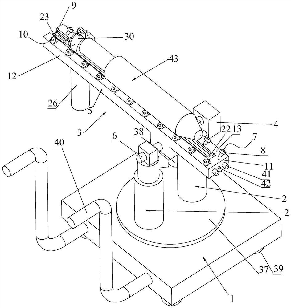
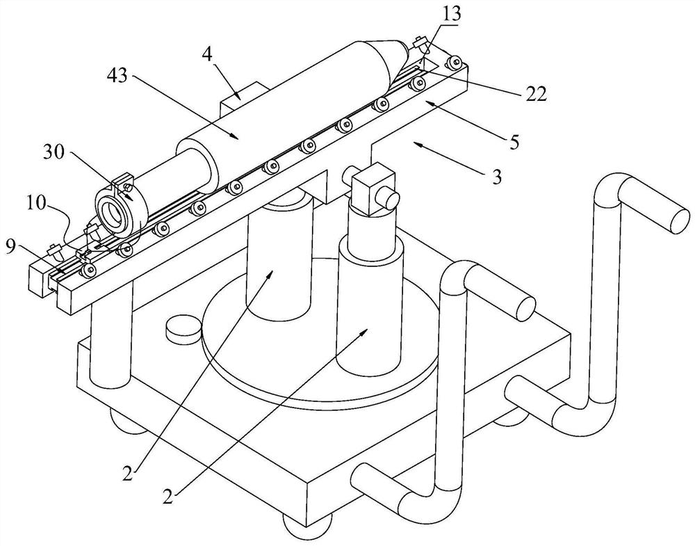
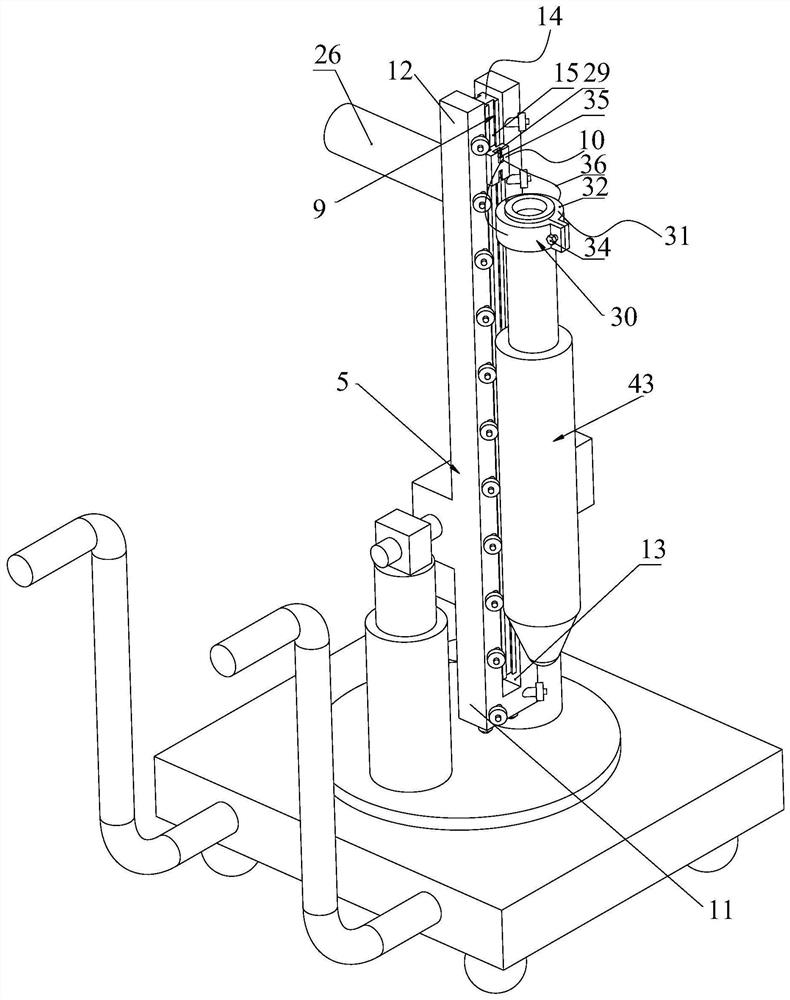
[0049] like Figure 1-7As shown, a transport and release device for preforms includes a movable base 1, a lift element 2, a transport and release mechanism 3, and a switching motor 4; the lift element 2 is installed on the movable base 1, and the transport and release mechanism 3 is installed in rotation. On the upper end of the lifting element 2, the switching motor 4 is used to drive the operation and amplifier mechanism 3 to rotate as a whole;

[0050] The operational amplifier mechanism 3 includes:

[0051] The support frame 5 is installed on the upper end of the lifting element 2 by rotating the rotating shaft 6. The support frame 5 has a horizontal working position and an inclined working position, and the switching motor 4 is used to drive the supporting frame 5 to switch between the horizontal working position and the inclined working position;

[0052] A plura...


PUM


Abstract

The invention discloses an operation and placement device for preforms. The operation and placement device comprises a movable base, a lifting element, an operation and placement mechanism and a switching motor; the lifting element is installed on the movable base, the operation and placement mechanism is rotationally installed at the upper end of the lifting element, and the switching motor is used for driving the operation and placement mechanism to rotate integrally. The operation and placement mechanism comprises a supporting frame rotationally installed at the upper end of the lifting element, a plurality of supporting roller groups arranged at intervals and are mounted on the supporting frame, and a push-pull assembly; each supporting roller group comprises two rollers which are symmetrically arranged; the push-pull assembly is provided with a moving block capable of reciprocating in the length direction of the supporting frame, and the moving block is used for being connected with the preform; when the supporting frame is located at the horizontal working position, the moving block is used for driving the preform to move in the length direction of the supporting frame, and when the supporting frame is located at the inclined working position, the moving block is used for driving the vertical preform to move up and down. The operation and placement device for the preform can flexibly operate, pick and place the preform without the aid of a crane.

Description

technical field [0001] The invention relates to the field of optical fiber prefabricated rods, in particular to a transport and amplifier device for the preformed rods. Background technique [0002] The casing method has the characteristics of high production efficiency and low cost. In actual operation, the tail pipe is welded at one end of the sleeve, and then the mandrel is inserted into the sleeve through the tail pipe to form a preform, and then the preform composed of the sleeve and mandrel is sent to the wire drawing furnace for wire drawing. At the same time, the clamping device above the wire drawing furnace clamps the tail pipe. [0003] In the existing production process, mandrels, casings, prefabricated rods, etc. are all operated by a transfer trolley and a crane in the workshop. The loading position needs to be within the stroke of the crane, which is more restricted and inconvenient to operate. Contents of the invention [0004] Aiming at the above problem...

Claims


Application Information

Patent Timeline
Patent Type & Authority Applications(China)
IPC IPC(8): B62B3/02B62B3/04
CPCB62B3/02B62B3/04B62B2203/72B62B2203/74
Inventor 吴海港
Owner HANGZHOU FUTONG COMM TECH CO LTD
Why Eureka
Try Eureka