Combined type single-row rotor wing tilting aircraft
A technology of rotor tilting and aircraft, applied in the field of aircraft, to achieve the effect of light wing, easy operation and simple structure
- Summary
- Abstract
- Description
- Claims
- Application Information
AI Technical Summary
Problems solved by technology
Method used
Image

Examples
Embodiment 1
[0025] The aircraft has coaxial twin rotors.
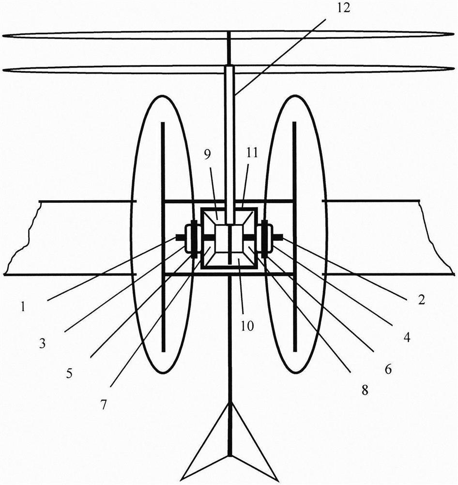
[0026] A composite single row rotor tilting aircraft includes a fuselage, wings and an empennage. The aircraft has a frame, and a fixed wing is connected to both sides of the frame. The wingtips of the fixed wing have two electric propellers arranged side by side and connected to a short rod. The short rod connected to the electric propeller is connected to the fixed wing. On the top, the short rod connected to the electric propeller is also connected to the output end where the steering gear is installed on the fixed wing.
[0027] There is an empennage behind the frame, and the empennage is connected with the ducted oars whose rotating shaft is vertically installed with the empennage design as one.
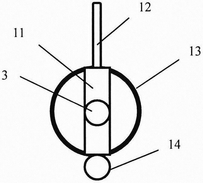
[0028] A rotor frame 11 is arranged in the center between the fixed wings on both sides of the frame, and the rotor frame 11 is connected with a first tilting shaft 3 and a second tilting shaft 4, and the first tilting shaft 3 and ...
Embodiment 2
[0035] The front blade and the rear blade of the coaxial dual rotor can also be connected to the rotor frame 11 by a support member.
[0036] A support tube set on the outer shaft of the rotor shaft 12 is fixedly connected to the rotor frame 11. The front end of the support tube is connected to a branch tube set on the support tube. Fixed on the branch pipe, the front propeller hub is keyed to the inner shaft, and the branch pipe is keyed to the outer shaft.
Embodiment 3
[0038] The aircraft may also have a rotor.
[0039] Rotor is connected on the rotor shaft 12. Alternatively, a set of support tubes sleeved on the rotor shaft 12 is fixedly connected to the rotor frame 11 , the rotor is connected to the support tube, and the rotor hub and the rotor shaft 12 are keyed.
[0040] Rotor shaft 12 is connected on the rotor frame 11 through the axis of the tilting shaft that rotor frame 11 is connected, and rotor shaft 12 can tilt back and forth between horizontal and vertical directions under the drive of tilting mechanism. Rotor shaft 12 connects a 3rd bevel gear 9 or the 4th bevel gear 10 at its rear end, the 3rd bevel gear 9 or the 4th bevel gear 10 and the first bevel gear 7 that the first power rotating shaft 1 is connected and the second power The second bevel gear 8 connected to the rotating shaft 2 is meshed and connected.
PUM
 Abstract
Description
Claims
Application Information
 - R&D
- Intellectual Property
- Life Sciences
- Materials
- Tech Scout
- Unparalleled Data Quality
- Higher Quality Content
- 60% Fewer Hallucinations
Browse by: Latest US Patents, China's latest patents, Technical Efficacy Thesaurus, Application Domain, Technology Topic, Popular Technical Reports.
© 2025 PatSnap. All rights reserved.Legal|Privacy policy|Modern Slavery Act Transparency Statement|Sitemap|About US| Contact US: help@patsnap.com