Detection circuit, adjustment method and detection method of output power, and phased array radar

A technology of output power detection and output power, which is applied in the direction of measuring device, radio wave measurement system, radio wave reflection/re-radiation, etc. It can solve the problem that the detection accuracy of output power cannot be detected, and the linear detection range of AD detection chip cannot meet the requirements of phase control. Radar array test needs and other issues to achieve the effect of reducing workload and ensuring measurement results

Active Publication Date: 2022-01-07
HUNAN EASTONE WASHON TECH CO LTD
View PDF24 Cites 5 Cited by
  • Summary
  • Abstract
  • Description
  • Claims
  • Application Information

AI Technical Summary

Problems solved by technology

[0012] The purpose of the present invention is to provide an output power detection circuit, an adjustment method, a detection method and a phased array radar, to solve the problem that the linear detection range of the AD detection chip cannot meet the test needs of the wide dynamic range of the phased array radar, and the 200MHz frequency band The problem that the output power cannot be detected accurately in real time and meets the detection accuracy requirements within the range

Method used


Image

  • Detection circuit, adjustment method and detection method of output power, and phased array radar
  • Detection circuit, adjustment method and detection method of output power, and phased array radar
  • Detection circuit, adjustment method and detection method of output power, and phased array radar

Examples


Embodiment Construction

[0050] The technical solutions in the present invention are clearly and completely described below in combination with the accompanying drawings in the embodiments of the present invention. Obviously, the described embodiments are only some of the embodiments of the present invention, not all of them. Based on the embodiments of the present invention, all other embodiments obtained by persons of ordinary skill in the art without creative efforts fall within the protection scope of the present invention.

[0051] The technical solution of the present application will be described in detail below with specific embodiments. The following specific embodiments may be combined with each other, and the same or similar concepts or processes may not be repeated in some embodiments.

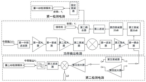
[0052] like figure 1 As shown, an output power detection circuit provided in this embodiment includes a power output circuit, a power detection circuit and a control circuit; the power output circuit incl...


PUM


Abstract

The invention discloses a detection circuit of output power. The detection circuit comprises a power output circuit, a power detection circuit and a control circuit; the power output circuit comprises a first intermediate frequency filter, a first amplifier, a first attenuator, a second amplifier, a second attenuator, a first mixer, a first filter, a third amplifier, a first coupler, a third attenuator, a fourth attenuator, a second filter and a second coupler; the power detection circuit comprises a first detection circuit and a second detection circuit; the first detection circuit comprises a fixed attenuator, the input end of the fixed attenuator is connected with the coupling end of the second coupler, and the output end of the fixed attenuator is connected with a first AD detection module; and the second detection circuit comprises a fifth attenuator, a fourth amplifier, a fifth amplifier, a second mixer, a third filter, a second intermediate frequency filter, a first single-pole double-throw switch and a second single-pole double-throw switch. The circuit can realize power output in a range of more than 95dB, and can carry out real-time detection.

Description

technical field [0001] The invention belongs to the technical field of power detection, and in particular relates to a wide bandwidth output power detection circuit, an adjustment method, a detection method and a phased array radar. Background technique [0002] According to the requirements of "X-band Dual Linear Polarization One-dimensional Phased Array Weather Radar System Functional Specification Requirements", the X-band phased array radar requires the following requirements: 1. The dynamic range should be above 95dB; 2. The working frequency band should be 9.3GHz~9.5GHz . [0003] In order to meet the above requirements, it is necessary to achieve a dynamic range of more than 95dB within 200MHz, and to be able to accurately measure the dynamic range. There are two specific implementation methods for accurate measurement: [0004] One is manual testing, that is, offline testing. Offline testing has high requirements for testing sites and equipment, and it is not conven...

Claims


Application Information

Patent Timeline
Patent Type & Authority Applications(China)
IPC IPC(8): G01S7/40G01S13/02
CPCG01S7/4021G01S13/02G01S2013/0245
Inventor 徐林玲兰才华
Owner HUNAN EASTONE WASHON TECH CO LTD
Why Eureka
Try Eureka