High-sulfur concentrate pump slurry feeding equipment and anti-blocking device and installation method thereof

A technology of sulfur concentrate and concentrate, which is applied in the direction of fixtures, mechanical equipment, cleaning methods and appliances, etc., can solve the problem that the sulfur concentrate pump cannot be guaranteed to run normally for a long time, and the sand accumulation in the slurry inlet pipe of the sulfur concentrate pump sinks , abnormal operation of the sulfur concentrate pump, etc., to reduce the risk of pipe plugging, reduce the severity of pipe plugging accidents, and achieve the effect of simple structure

Pending Publication Date: 2022-01-11
SHUI KOU SHAN NONFERROUS METALS LTD
View PDF0 Cites 0 Cited by
  • Summary
  • Abstract
  • Description
  • Claims
  • Application Information

AI Technical Summary

Problems solved by technology

[0005] The invention provides an anti-blocking device for the slurry inlet pipe of the sulfur concentrate pump, which aims to solve the problem of the blockage of the slurry inlet pipe of the existing sulfur concentrate pump by the sulfur concentrate pulp and the occurrence of internal accumulation in the slurry delivery pipe of the sulfur concentrate pump for a long time. Sand subsidence causes blockage, which cannot guarantee the normal operation of the sulfur concentrate pump for a long time
[0006] The invention also provides a high-sulfur concentrate pump slurry feeding equipment, which solves the problems of slurry blockage in the existing equipment
[0007] The invention also provides a method for installing the slurry feeding equipment of the high-sulfur concentrate pump, which solves the problems of abnormal operation of the sulfur concentrate pump in the prior art

Method used


Image

  • High-sulfur concentrate pump slurry feeding equipment and anti-blocking device and installation method thereof
  • High-sulfur concentrate pump slurry feeding equipment and anti-blocking device and installation method thereof

Examples


Embodiment Construction

[0025] The following will clearly and completely describe the technical solutions in the embodiments of the present invention with reference to the accompanying drawings in the embodiments of the present invention. Obviously, the described embodiments are only some, not all, embodiments of the present invention. Based on the embodiments of the present invention, all other embodiments obtained by persons of ordinary skill in the art without creative efforts fall within the protection scope of the present invention.

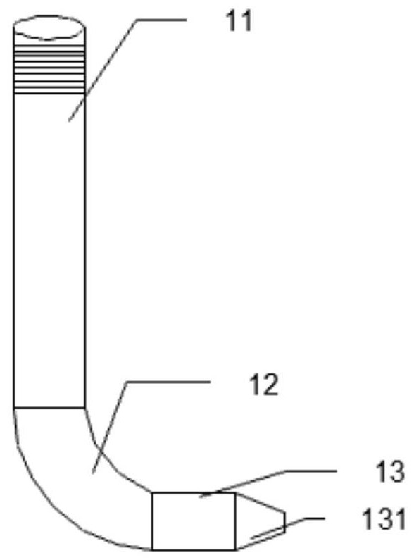
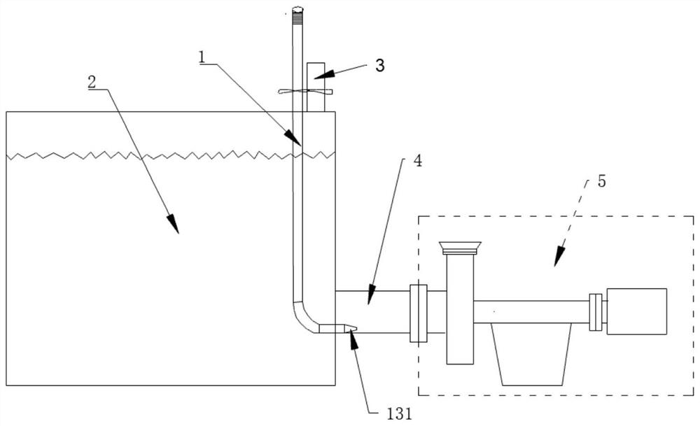
[0026] like figure 1 As shown, the anti-blocking device for the slurry inlet pipe of the high-sulfur fine pump includes a pipeline one 11, an elbow 12 and a pipeline two 13, the water inlet of the elbow 12 communicates with the outlet of the pipeline one 11, and the elbow The water outlet of 12 communicates with the water inlet of pipeline 2 13, the water inlet of described pipeline 1 11 is used to communicate with the water outlet of faucet, and the water outlet o...


PUM


Abstract

The invention provides a high-sulfur concentrate pump slurry inlet pipe anti-blocking device which comprises a first pipeline, a bent pipe and a second pipeline, wherein a water inlet of the bent pipe is communicated with a water outlet of the first pipeline, a water outlet of the bent pipe is communicated with a water inlet of the second pipeline, and the water inlet of the first pipeline is used for being communicated with a water outlet of a faucet. A water outlet of the pipeline II is formed in the bottom of the slurry inlet pipe of the sulfur concentrate pump. The invention further provides pulp feeding equipment of the high-sulfur concentrate pump. The invention further provides a mounting method of the anti-blocking device for the slurry inlet pipe of the high-sulfur concentrate pump. According to the anti-blocking device for the pulp inlet pipe of the high-sulfur concentrate pump, when sulfur concentrate pulp conditions change, the pulp inlet pipe of the sulfur concentrate pump cannot be blocked, and it is ensured that pulp in a pulp conveying pipe cannot be cut off, and the water pressure is enough to flush and disperse the pulp foam. The anti-blocking device for the slurry inlet pipe of the high-sulfur concentrate pump is simple in structure, small in size and convenient to install and operate.

Description

technical field [0001] The invention relates to an anti-blocking device for a slurry inlet pipe of a sulfur concentrate pump. Background technique [0002] The sulfur concentrate produced by the flotation process of the sulfur concentrate ore concentrator is generally a foam product with a sulfur grade of 35%-45%. The main mineral is pyrite, and the mineral specificity is large, generally 5.2-6.2. After the sulfur concentrate foam is washed away by water, the sulfur concentrate is prone to sink. During the long-distance (more than 200 meters) pipeline transportation with a steep slope, sulfur concentrate pipeline blockage accidents often occur, causing metal loss, leading to environmental accidents. Among the many causes of pipe plugging, the main reasons are high pulp concentration, large amount of pulp, and sticky pulp foam. [0003] In the existing production technology, it is only solved by adding additional water above the slurry level in the sulfur concentrate pump p...

Claims


Application Information

Patent Timeline
Patent Type & Authority Applications(China)
IPC IPC(8): B03D1/14B08B9/032F16B1/02F17D1/08
CPCB03D1/1468B03D1/1462B08B9/0321F17D1/088F16B1/02
Inventor 田茂兵钟平海
Owner SHUI KOU SHAN NONFERROUS METALS LTD
Why Eureka
Try Eureka