LED driving lamp strip

A technology of light strips and lamp sockets, which is applied in the direction of motor vehicles, road vehicles, vehicle parts, etc., can solve the problems of limited fixing method and installation angle, flexible light strips cannot adjust the lighting angle, and hard light strips are inconvenient to bend, etc. , to achieve the effect of convenient adjustment, improved disassembly efficiency and strong practicability

Inactive Publication Date: 2022-01-11
深圳市金风驰科技有限公司
View PDF0 Cites 0 Cited by
  • Summary
  • Abstract
  • Description
  • Claims
  • Application Information

AI Technical Summary

Problems solved by technology

[0006] In order to overcome the disadvantages that the lighting angle cannot be adjusted after the flexible light strip is fixed, and the use cost is high; the hard light strip is not easy to bend, and the fixing method and installation angle are limited. The technical problem to be solved by the present invention is to provide a An LED driving light strip with adjustable lighting angle, long service life, low cost, and flexible installation angle

Method used


Image

  • LED driving lamp strip
  • LED driving lamp strip
  • LED driving lamp strip

Examples


Embodiment 1

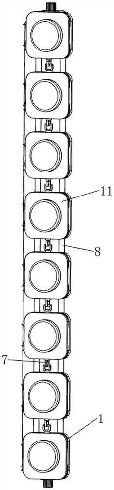
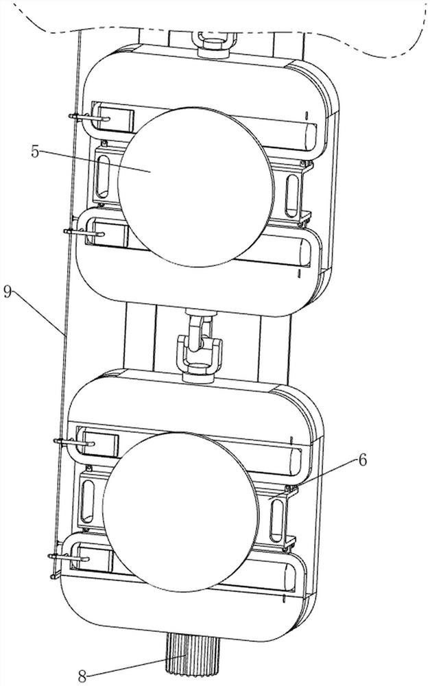
[0037] A LED running light strip, such as Figure 1-8 As shown, it includes a lamp holder 1, a limit slot plate 3, a first power supply seat 4, a lamp bead 5, a clamping assembly 6 and a movable connection assembly 7. There are eight lamp holders 1, and the eight lamp holders 1 are arranged from above It is evenly distributed in a straight line from the bottom to the bottom. There is a movable connection assembly 7 connected between each two adjacent lamp holders 1. There are installation grooves 2 on the front sides of multiple lamp holders 1. The installation grooves 2 are square. The lamp holders The middle part of the installation groove 2 of 1 is connected with the first power supply seat 4 by means of screw connection, and the upper and lower sides of the front end of the lamp holder 1 are integrally formed with a limiting slot plate 3, and two limiting slot plates 3 of each lamp holder 1 A clamping assembly 6 is clamped and connected between them, and a lamp bead 5 is i...

Embodiment 2

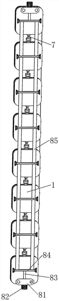
[0044] On the basis of Example 1, such as figure 1 , figure 2 , Figure 9 , Figure 10 , Figure 11 , Figure 12 and Figure 13 As shown, an adjustment assembly 8 is also included. The adjustment assembly 8 includes a connecting plate 81, a handle 82, a connecting shaft 83, a first connecting rod 84 and a rope 85. A connecting shaft 83 is connected in a screw connection, and a connecting plate 81 is rotatably connected to the connecting shaft 83. The connecting plate 81 is sleeved on the outside of the connecting shaft 83, and the end of the connecting shaft 83 is connected with a handle 82 through a key connection. The middle part of the rear end surface of each lamp holder 1 is connected horizontally with a first connecting rod 84, the upper connecting shaft 83 is welded to the middle of the uppermost first connecting rod 84, and the lower connecting shaft 83 is connected to the lowermost first connecting rod 84. The middle part is welded and connected, and there are ...


PUM


Abstract

The invention relates to a lamp strip, in particular to an LED driving lamp strip. The technical problem to be solved by the invention is to provide the LED driving lamp strip which is adjustable in illumination angle, long in service life, low in cost and flexible and changeable in mounting angle. In order to solve the technical problem, the invention provides the LED driving lamp strip which comprises lamp holders, a limiting groove plate, a first electrifying seat, a lamp bead, movable connecting assemblies and the like; and the multiple lamp holders are evenly distributed in a straight line from top to bottom, a movable connecting assembly is connected between every two adjacent lamp holders, mounting grooves are formed in the front sides of the multiple lamp holders, and first power-on bases are connected to the middles of the mounting grooves of the lamp holders. The lamp beads can be conveniently replaced through clamping assemblies, the shape of the lamp strip can be adjusted according to needs through the arranged movable connecting assemblies, multi-angle rotation is achieved, and the lamp strip can be conveniently fixed to curved surfaces with different amplitudes.

Description

technical field [0001] The invention relates to a light strip, in particular to an LED running light strip. Background technique [0002] With the rapid development of society, there are more and more styles of cars. To make the car more beautiful when driving, light strips are generally installed on the front of the car or the parking space. [0003] The current light strips are generally divided into two types, one is soft light strips, although this kind of light strips are soft and can be curled arbitrarily, they can only be fixed and installed on the surface of the car shell with 3M double-sided adhesive tape. The lighting angle cannot be adjusted, and this kind of light strip has silica gel as the outer protective layer, its surface is easy to corrode, and its practical life is short, and when the light strip is damaged, it is impossible to replace a single or multiple lamp beads, and the whole strip needs to be followed. The replacement cost is high; the other is a h...

Claims


Application Information

Patent Timeline
Patent Type & Authority Applications(China)
IPC IPC(8): B60Q1/26F21S4/20F21V15/00F21V17/10F21V17/16F21V19/04F21V21/14F21W107/10F21Y115/10
CPCB60Q1/26F21S4/20F21V21/14F21V19/04F21V15/00F21V17/104F21V17/16F21W2107/10F21Y2115/10
Inventor 李明
Owner 深圳市金风驰科技有限公司
Why Eureka
Try Eureka