Scroll compressor

A scroll compressor and movable scroll technology, which is applied in the field of scroll compressors, can solve the problems of easy wear of wear-resistant coatings and easy wear of contact surfaces.

Pending Publication Date: 2022-01-11
EMERSON CLIMATE TECH (SUZHOU) CO LTD
View PDF0 Cites 0 Cited by
  • Summary
  • Abstract
  • Description
  • Claims
  • Application Information

AI Technical Summary

Problems solved by technology

However, in the case of high load, the wear-resistant coating is easily worn away, so that the contact surface of the thrust plate and the or

Method used


Image

  • Scroll compressor
  • Scroll compressor
  • Scroll compressor

Examples


Embodiment Construction

[0051] The following descriptions of various embodiments of the present invention are exemplary only, and in no way limit the present invention and its application or usage. The same reference numerals are used to denote the same types of components in the respective drawings, and the configuration of the same components will not be described repeatedly.

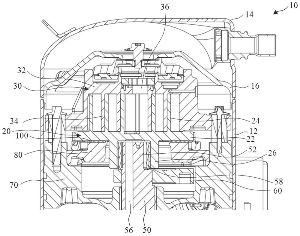
[0052] will now refer to figure 1 The basic construction and operating principle of the scroll compressor according to the present invention will be described. Scroll compressor 10 includes a generally cylindrical housing 12 . An intake joint (not shown) is provided on the shell 12 for sucking in low-pressure gaseous refrigerant. One end of the shell 12 is fixedly connected with an end cover 14 , and the other end is fixedly connected with a bottom cover (not shown). The end cap 14 is fitted with a discharge connection for discharging the compressed refrigerant. A partition 16 extending transversely relative to the casin...


PUM


Abstract

The invention discloses a scroll compressor. The scroll compressor comprises a fixed scroll component, a movable scroll component, a rotating shaft, a bearing seat and a thrust plate, wherein the movable scroll component is matched with the fixed scroll component to form a compression mechanism for compressing working fluid, and the movable scroll component comprises a movable scroll end plate; the rotating shaft is used for driving the movable scroll component, so that the movable scroll component moves relative to the fixed scroll component so as to compress the working fluid; the rotating shaft is rotationally supported on the bearing seat; and the thrust plate is arranged between the movable scroll component and the bearing seat, and the movable scroll end plate is supported on the thrust plate in a sliding manner. An independent wear-resistant part is arranged between the movable scroll end plate and the thrust plate.

Description

technical field [0001] The invention relates to a scroll compressor, in particular to a scroll compressor in which a separate wear-resistant part is arranged between the movable scroll end plate and the thrust plate of the scroll compressor. Background technique [0002] In a scroll compressor, the compression of fluid is achieved through the relative motion between the orbiting scroll member and the fixed scroll member. In order to provide axial support for the movable scroll part, a thrust plate is provided on one side of the end plate of the movable scroll part. The thrust plate is fixed to or formed in one piece with the bearing housing. During the operation of the compressor, the movable scroll part moves in translation relative to the thrust plate, and the thrust plate is directly in contact with the movable scroll part. Usually, the thrust plate and orbiting scroll parts are made of cast iron, and the contact surfaces are finely machined. Sometimes it is necessary ...

Claims


Application Information

Patent Timeline
IPC IPC(8): F04C18/02F04C29/00
CPCF04C18/0215F04C29/00F04C2240/801
Inventor 韩艳春许美玲缪仲威赵景莲
Owner EMERSON CLIMATE TECH (SUZHOU) CO LTD
Why Eureka
Try Eureka