Ceramic bearing structure for rotor shaft and water-lubricated screw compressor

A technology of screw compressors and ceramic bearings, applied in the directions of shafts and bearings, rotating bearings, bearings, etc., can solve the problems of low assembly efficiency, occupation, long length of the water-lubricated screw compressor host, etc., and achieve easy assembly or disassembly. The process is simple, the lubrication effect is good, and the assembly efficiency is improved.

Pending Publication Date: 2022-01-11
NINGBO BAOSI ENERGY EQUIP
View PDF0 Cites 0 Cited by
  • Summary
  • Abstract
  • Description
  • Claims
  • Application Information

AI Technical Summary

Problems solved by technology

[0002] Oil-free screw compressors are widely used in petroleum, chemical, food, medicine and other fields, and the market demand is becoming more and more urgent. Water-lubricated screw compressors, as a completely oil-free compressor, conform to the development trend of the market and are currently used in screw rotors. The water-lubricated bearings generally use ceramic bearings, which have the characteristics of high temperature resistance, wear resistance, corrosion resistance, oil-free self-lubrication, high speed, etc. The assembly of water-lubricated ceramic bearings and rotor shafts basically adopts taper fit or interference When assembling, the bearing needs to be heated first, and the axial direction must rely on lock nuts, compression end caps and screws or lock with expansion sleeves. This not only reduces the assembly efficiency, but also reduces the A considerable section of the rotor will be occupied, resulting in a longer length of the main body of the water-lubricated screw compressor. Moreover, when locking the water-lubricated bearings, the screw rotor needs to be fixed all the time, and there is a certain degree of difficulty in assembling or disassembling. Difficulty, and it is not easy for the assembler to control the torque that needs to be applied for locking

Method used


Image

  • Ceramic bearing structure for rotor shaft and water-lubricated screw compressor
  • Ceramic bearing structure for rotor shaft and water-lubricated screw compressor
  • Ceramic bearing structure for rotor shaft and water-lubricated screw compressor

Examples


Embodiment 1

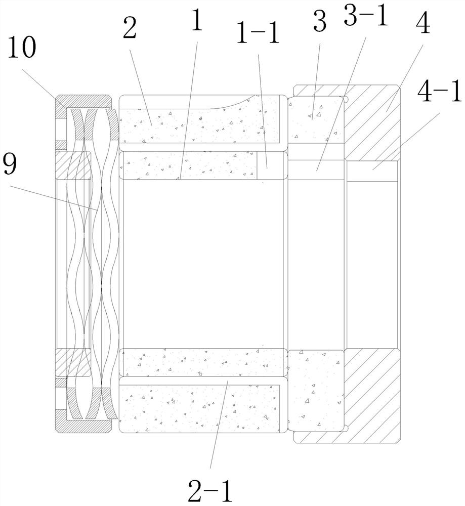
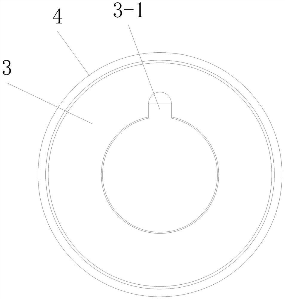
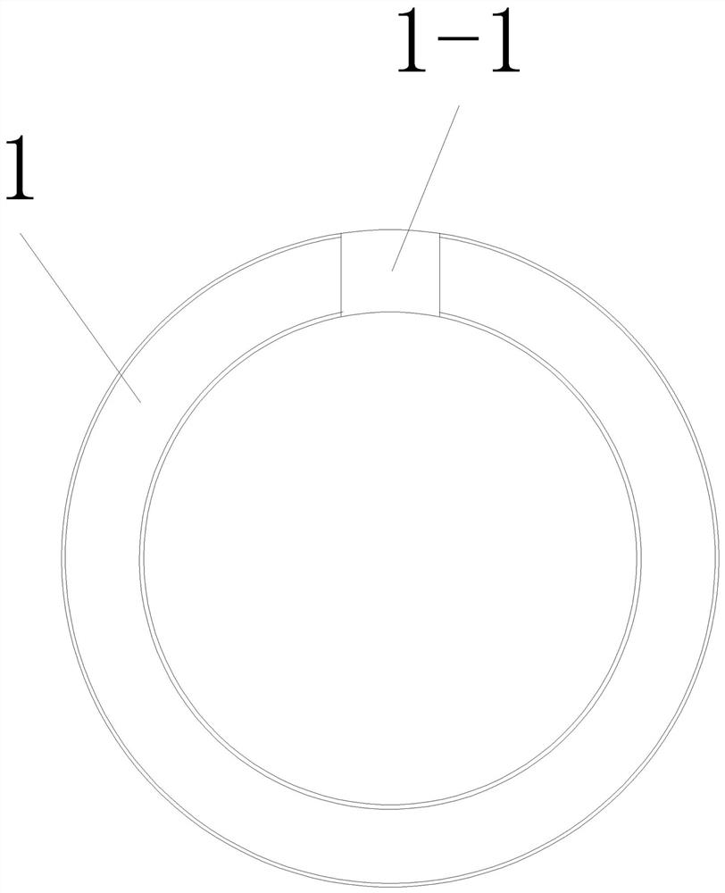
[0024] Such as Figure 1 to Figure 4 As shown in , the ceramic bearing structure for the rotor shaft of the present invention includes a sliding bearing 1, a bearing bush 2, a thrust bearing 3, and a thrust bearing seat 4, and the thrust bearing 3 is fixedly connected in the thrust bearing seat 4, and the sliding bearing 1, the thrust bearing 3 and The thrust bearing housing 4 is provided with an inner hole for socketing the rotor shaft, and the side walls of the inner holes of the sliding bearing 1, the thrust bearing 3 and the thrust bearing housing 4 are respectively provided with a first key groove 1 for key connection with the rotor shaft -1. The second keyway 3-1, the third keyway 4-1, the first keyway 1-1, the second keyway 3-1, and the third keyway 4-1 can be connected end to end to form a large keyway, sliding bearing 1, bearing bush 2. The thrust bearing 3 is made of ceramic material. In this embodiment, silicon carbide material can be used, and zirconia material can...

Embodiment 2

[0026] Such as Figure 5As shown in , the water-lubricated screw compressor of the present invention includes a compressor main body, a screw rotor 6 is arranged in the cylinder of the compressor main body, and a bearing hole is arranged on the casing of the compressor main body, and a bearing hole such as The ceramic bearing structure and the elastic pretensioner for the rotor shaft described in Embodiment 1, the elastic pretensioner includes a wave spring 9 and a spring seat 10, the wave spring 9 is arranged in the spring seat 10, and the spring seat 10 is also provided with a shaft sleeve, the wave spring 9 is limited between the outer wall of the sleeve and the inner wall of the spring seat 10, the sleeve is sleeved on the screw rotor 6, the spring seat 10 is limited in the bearing hole, and the side wall of the bearing hole A positioning screw 8 is provided, and the positioning screw 8 is in contact with and pressed against the bottom of the positioning groove 2-2 of the ...


PUM


Abstract

The invention relates to a ceramic bearing structure for a rotor shaft and a water-lubricated screw compressor. The ceramic bearing structure for the rotor shaft comprises a sliding bearing made of a ceramic material, a bearing bush and a thrust bearing; the inner side of the sliding bearing and the inner side of the thrust bearing are each provided with a key groove used for being in key connection with the rotor shaft, and the sliding bearing is used for supporting the rotor shaft in the radial direction; the bearing bush is in clearance fit with the outer side wall of the sliding bearing; at least one positioning groove is formed in the outer side wall of the bearing bush; a plurality of water guiding grooves are formed in the inner side wall of the bearing bush; a plurality of water diversion grooves communicated with the water guiding grooves are formed in the end face of the bearing bush, and the end face of the thrust bearing makes contact with the end face of the bearing bush; and the thrust bearing is used for axially supporting the rotor shaft and axially limiting the bearing bush. The water-lubricated screw compressor adopts the ceramic bearing structure for the rotor shaft, the rotor shaft rotating at a high speed can be controlled to move in the axial direction and the radial direction, the assembly or disassembly process is simple, and the assembly efficiency can be greatly improved.

Description

technical field [0001] The invention relates to the technical field of oil-free compressors, in particular to a ceramic bearing structure for a rotor shaft and a water-lubricated screw compressor. Background technique [0002] Oil-free screw compressors are widely used in petroleum, chemical, food, medicine and other fields, and the market demand is becoming more and more urgent. Water-lubricated screw compressors, as a completely oil-free compressor, conform to the development trend of the market and are currently used in screw rotors. The water-lubricated bearings generally use ceramic bearings, which have the characteristics of high temperature resistance, wear resistance, corrosion resistance, oil-free self-lubrication, high speed, etc. The assembly of water-lubricated ceramic bearings and rotor shafts basically adopts taper fit or interference When assembling, the bearing needs to be heated first, and the axial direction must rely on lock nuts, compression end caps and ...

Claims


Application Information

Patent Timeline
Patent Type & Authority Applications(China)
IPC IPC(8): F16C17/04F16C33/04F16C35/02F16N1/00F16N15/04F04C29/00F04C29/02
CPCF16C17/04F16C33/043F16C35/02F16N1/00F16N15/04F04C29/00F04C29/0007F04C29/02F16N2210/14F04C2240/50
Inventor 周坤马升庄博胡伟
Owner NINGBO BAOSI ENERGY EQUIP
Why Eureka
Try Eureka