Automatic liquid level glue injection detection device and automatic liquid level glue injection method

An automatic detection device and glue injection technology, which is used in measuring devices, liquid level indicators, lubrication indicating devices, etc., can solve the problems of complex glue injection process control and high cost, and achieve high control accuracy, low cost and simple structure. Effect

Pending Publication Date: 2022-01-11
XIAN MICROELECTRONICS TECH INST
View PDF3 Cites 2 Cited by
  • Summary
  • Abstract
  • Description
  • Claims
  • Application Information

AI Technical Summary

Problems solved by technology

[0006] In order to overcome the shortcomings of the above-mentioned prior art, the injection process of the open potting mold is complicated to control and the cost is high, the object of the present invention is to provide an automatic detection device for liquid surface injection and an automatic liquid surface injection method

Method used


Image

  • Automatic liquid level glue injection detection device and automatic liquid level glue injection method
  • Automatic liquid level glue injection detection device and automatic liquid level glue injection method
  • Automatic liquid level glue injection detection device and automatic liquid level glue injection method

Examples


Embodiment 1

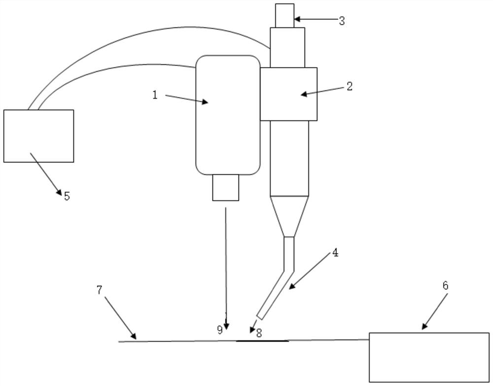
[0040] A liquid level glue injection automatic detection device, such as figure 1 As shown, it includes a control unit 5 and a monitoring unit electrically connected to the control unit 5;

[0041] The detection unit includes a range finder 1, a switching valve 2 and a glue injection pipeline 3. The distance gauge 1 is equipped with a probe, which is located directly above the glue injection point. The switch valve 2 is installed on the glue injection pipeline 3 and is located at the distance measuring On the side of the outer wall of the meter 1, the glue injection pipeline 3 and the rangefinder 1 are all vertically arranged, the inlet end of the glue injection pipeline 1 is connected to the outlet of the external glue injection raw material, and the outlet end of the glue injection pipeline 1 is connected to an oblique glue injection device. The head 4, the outlet end of the oblique glue injection head 4 is located above the glue injection point; the rangefinder 1 and the sw...

Embodiment 2

[0043] Except for the following content, all the other contents are the same as in Example 1.

[0044]The control unit 5 includes a controller and a display electrically connected to the controller. The range finder 1 is a laser range finder. The distance between the probe of the rangefinder 1 and the glue injection point is 10 mm to 40 mm; the angle between the horizontal plane where the inclined glue injection head 4 and the glue injection point is located is 45° to 60°; The distance between glue points is 0mm~2mm.

[0045] It should be noted that the specific time needs to be determined by programming according to the specific experiment of the leveling and liquid surface sinking time jointly formed by the viscosity of the glue and the internal shape of the potting structure. The liquid with higher viscosity generally has a slower leveling speed; the internal cavity structure is complex and the gap is narrow, and the sinking speed of the liquid surface will also be slowed...

Embodiment 3

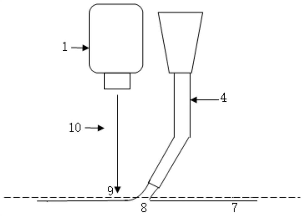
[0047] A glue injection method based on the automatic liquid level control of the liquid level glue injection automatic detection device, such as figure 2 shown, including the following steps:

[0048] Step 1) Install the oblique glue injection head 4, adjust the inclination angle of the oblique glue injection head 4, so that the glue liquid flowing out of the outlet end of the oblique glue injection head 4 is located on the glue injection point, and the glue injection point is located on the rangefinder 1 The light spot detection point of the upper probe;

[0049] Step 2) The control unit 5 controls the switch valve 2 to open, so that the glue is injected through the glue injection pipeline 3 and the inclined glue injection head 4, and the control unit 5 is provided with a preset height;

[0050] Step 3) The rangefinder 2 measures the height of the glue injection, and transmits the measured real-time glue injection height to the control unit 5, and the control unit 5 receiv...


PUM


Abstract

The invention discloses an automatic liquid level glue injection detection device and an automatic liquid level glue injection method, and belongs to the technical field of automatic fluid control. A control unit, a laser height measuring probe, a switch valve and an inclined glue injection head are combined, so that the glue injection liquid level height is accurately controlled in a simple and convenient manner; the switch valve is used, the cost is low, the structure is simple, blockage is not prone to occurring, a metering pump with a complex and expensive structure is not used, and the control effect similar to that of the metering pump can be achieved. The device is simple in structure, easy to manufacture, good in stability, high in liquid level control precision, easy and convenient to use and high in efficiency, can achieve the effect similar to that of a metering pump, is suitable for various automatic glue injection schemes under the background of automation popularization, and has wide industrial application prospects.

Description

technical field [0001] The invention belongs to the technical field of automatic fluid control, and relates to an automatic liquid surface glue injection detection device and an automatic liquid surface glue injection method. Background technique [0002] In the field of potting technology, in order to ensure that the glue will not overflow the mold, or waste materials, or contaminate the workpiece, it is necessary to stably control the amount of glue injected. Glue level height. For the potting work where the upper mouth of the mold is open and the liquid level needs to be accurately maintained at a certain height after the final potting, the currently commonly used potting and injection solution is to use a metering pump to accurately calculate the amount of glue used, and then use the push rod Or bolt-type pump valve to precisely control the injection volume. However, since this type of control valve contains precision motion components, it needs to work in a liquid ero...

Claims


Application Information

Patent Timeline
Patent Type & Authority Applications(China)
IPC IPC(8): G05D9/12G01F23/292
CPCG05D9/12G01F23/292
Inventor 张丁王超
Owner XIAN MICROELECTRONICS TECH INST
Why Eureka
Try Eureka