Fence for reversible lane based on smart city and working method of fence

A technology of tidal lanes and working methods, applied in the directions of roads, roads, road signs, etc., can solve the problems of reducing the service life of the road, destroying the road, time-consuming and laborious, and achieving the effect of axial positioning and convenient installation.

Pending Publication Date: 2022-01-11
韩怀奇
View PDF11 Cites 0 Cited by
  • Summary
  • Abstract
  • Description
  • Claims
  • Application Information

AI Technical Summary

Problems solved by technology

[0003] Setting tidal lanes is an effective means to solve road traffic congestion. Less investment in construction costs can effectively alleviate traffic tidal phenomena, but tidal lanes need a long time to adapt, and many people who do not understand the situation during use Drivers from other places or local novice drivers who are not familiar with the traffic conditions are likely to drive in the tidal lane by mistake, and it is easy to cause traffic accidents. At present, there are guardrails to solve the tidal lane, but it still needs to be fixed every day manually or by vehicles. It is time-consuming and labor-intensive to move, and it is a large expense; some designed guardrails need to destroy the original road, and the initial investment in use is relatively large; this will cause certain damage to the original road subgrade and reduce road safety. service life

Method used


Image

  • Fence for reversible lane based on smart city and working method of fence
  • Fence for reversible lane based on smart city and working method of fence
  • Fence for reversible lane based on smart city and working method of fence

Examples


Embodiment Construction

[0030]The following are specific embodiments of the present invention and in conjunction with the accompanying drawings, the technical solutions of the present invention are further described, but the present invention is not limited to these embodiments.

[0031] In the description of the present invention, it should be noted that the orientation or positional relationship indicated by the terms "inner", "lower", etc. is based on the orientation or positional relationship shown in the drawings, or the conventionally placed position when the product of the invention is used. Orientation or positional relationship is only for the convenience of describing the present invention and simplifying the description, and does not indicate or imply that the referred device or element must have a specific orientation, be constructed and operated in a specific orientation, and thus should not be construed as a limitation of the present invention. In addition, the terms "first", "second", e...


PUM


Abstract

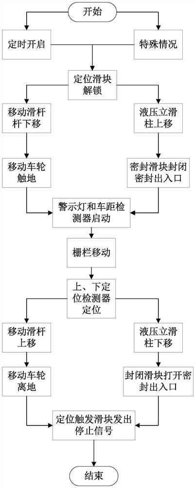
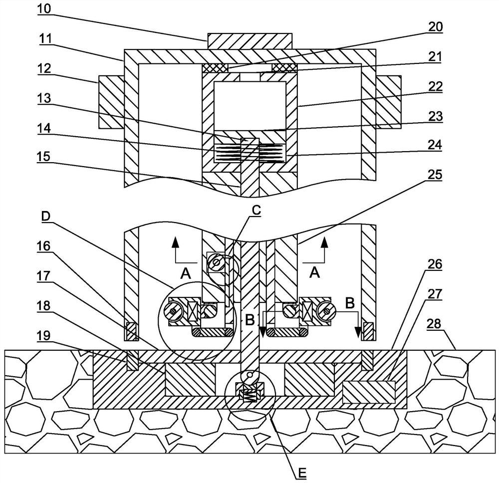
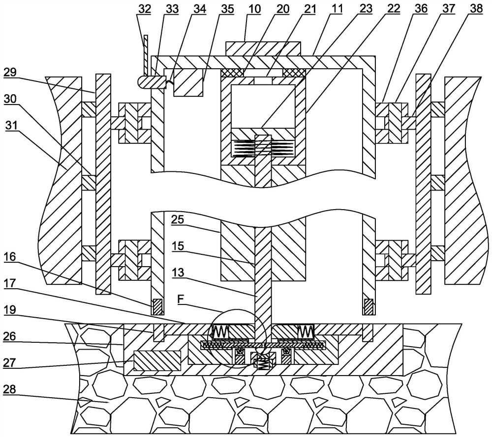
The invention belongs to the field of smart cities, and particularly relates to a fence for reversible lane based on a smart city and working methodthereof. The method is carried out in cooperation with the fence for the reversible lane based on the smart city and the working device of the fence. The fence for the reversible lane based on the smart city and the working device of the fence comprise an asphalt pavement, and a lower rack is fixedly arranged on the asphalt pavement; wherein a mounting rack is fixedly arranged in the lower rack, and a positioning mechanism is fixedly arranged on the mounting rack; an upper rack is fixedly arranged on the lower rack, a sealing mechanism is fixedly arranged on the upper rack, and a sealing inlet / outlet is formed in the upper rack; a hydraulic vertical sliding column abuts against the interior of the sealing inlet and outlet, and the hydraulic vertical sliding column abuts against an upper mounting rack. A moving power and control mechanism is arranged on the upper mounting rack, a hydraulic mechanism is arranged on the upper mounting rack, a damping rubber gasket is fixedly arranged on the hydraulic mechanism, and a stand column shell is fixedly arranged on the damping rubber gasket.

Description

technical field [0001] The invention belongs to the field of smart cities, and in particular relates to a fence for tidal lanes based on smart cities and a working method thereof. Background technique [0002] Due to the rapid economic development, there are more and more car owners. Driving to and from get off work makes personal time fully grasped and utilized. However, because the workplace is generally in the center of the city, and most of the residences are located in the surrounding areas, Caused the road traffic tide phenomenon around the city to be serious. Due to the "tide phenomenon" of traffic, that is, the traffic flow in the direction of the city is large every morning, and the traffic flow in the reverse direction is small; at night, the traffic flow in the direction of the city is large, which aggravates the congestion. In view of this situation, the traffic diversion transformation adopts the way of variable lanes for traffic organization, that is, when ther...

Claims


Application Information

Patent Timeline
Patent Type & Authority Applications(China)
IPC IPC(8): G08G1/09E01F9/615E01F9/669E01F15/00
CPCG08G1/09E01F15/006E01F9/617E01F9/669
Inventor 不公告发明人
Owner 韩怀奇
Why Eureka
Try Eureka