Power supply noise suppression circuit, suppression method and image sensor

A technology for image sensor and power supply noise, which is applied in circuits, image communication, electric solid-state devices, etc., can solve the problems of large occupied layout area, limited stable speed, performance degradation of image sensor chips, etc., and achieves resistance to power supply noise interference and reduces Image noise, the effect of improving image quality

Pending Publication Date: 2022-01-11
思特威(上海)电子科技股份有限公司
View PDF0 Cites 0 Cited by
  • Summary
  • Abstract
  • Description
  • Claims
  • Application Information

AI Technical Summary

Problems solved by technology

If the output of the LDO is affected, the power supply noise will still be reflected on the image. Therefore, when using the LDO to solve the power supply noise, when the chip interference is large, the stabilization speed of this method is limited. During the stabilization process, the power supply noise is still It will be reflected on the image, and the LDO also occupies a large layout area, consumes power and limits the power supply used by other modules, which may lead to a decrease in the performance of the image sensor chip

Method used


Image

  • Power supply noise suppression circuit, suppression method and image sensor
  • Power supply noise suppression circuit, suppression method and image sensor
  • Power supply noise suppression circuit, suppression method and image sensor

Examples


Embodiment Construction

[0031]In order to make the purpose, technical solutions and advantages of the present invention clearer, the technical solutions of the present invention will be clearly and completely described below in conjunction with the accompanying drawings. Apparently, the described embodiments are part of the embodiments of the present invention, rather than all of them. Examples are only used to explain the present invention, not to limit the present invention. Based on the embodiments of the present invention, all other embodiments obtained by persons of ordinary skill in the art without making creative efforts belong to the protection scope of the present invention. "One embodiment" or "an embodiment" in this patent specification means that a specific feature, structure or characteristic described in conjunction with the example is included in at least one embodiment of the present invention.

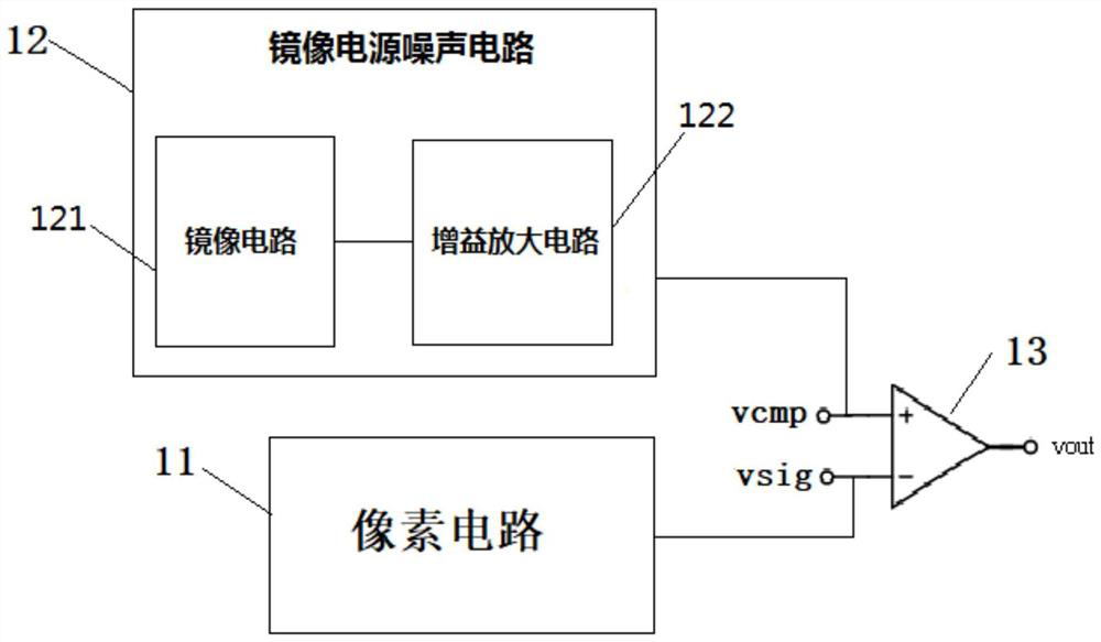
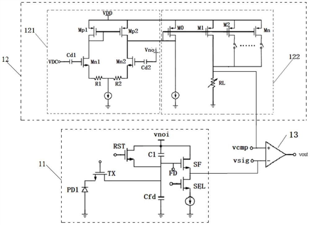
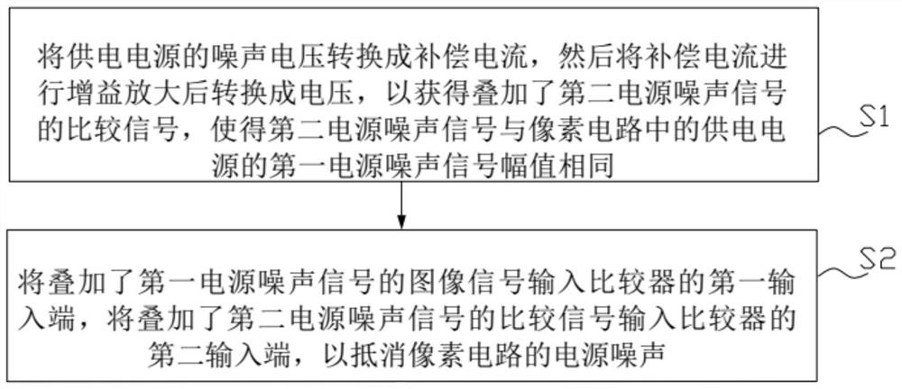
[0032] Please refer to figure 1 , figure 1 A structural block diagram of an image senso...


PUM


Abstract

The invention relates to a power supply noise suppression circuit and suppression method. The power supply noise suppression circuit comprises a pixel circuit, a mirror image power supply noise circuit and a comparator, an image signal of a first power supply noise signal of a power supply superposed in the pixel circuit is input into a first input end of the comparator, a comparison signal of a second power supply noise signal of the power supply superposed in the mirror image power supply noise circuit is input into a second input end of the comparator, and the amplitude of the second power supply noise signal is the same as that of the first power supply noise signal; and the mirror image power supply noise circuit comprises a mirror image circuit and a gain amplification circuit, the mirror image circuit is used for converting the noise voltage of the power supply into compensation current, and the gain amplification circuit is used for performing gain amplification on the compensation current and then converting the compensation current into voltage, and outputting the comparison signal to the second input end of the comparator. The power supply noise of the source electrode following transistor in the pixel circuit is suppressed through the power supply noise of the power supply in the mirror image power supply noise circuit, the power supply noise interference can be effectively resisted, the image noise is reduced, and the image quality is improved.

Description

technical field [0001] The invention relates to the field of image sensor electronic circuits, in particular to a power supply noise suppression circuit, a suppression method and an image sensor. Background technique [0002] Image sensors are commonly used in a variety of electronic devices, such as video surveillance systems, smart phones, digital cameras, and smart AI, face recognition, and other electronic products to capture and identify image information of people or scenes. As an important part of digital cameras, it provides the conversion of optical images into electrical signals. Image sensors can be divided into CMOS (Complementary Metaloxide Semiconductor, Complementary Metal Oxide Semiconductor), CCD (Charge Coupled Device, Charge Coupled Device) and image sensors according to different components. [0003] CMOS image sensors have the advantages of high integration, low power consumption, programmable random reading of local pixels, high speed and low cost, and...

Claims


Application Information

Patent Timeline
Patent Type & Authority Applications(China)
IPC IPC(8): H04N5/357H04N5/374
CPCH04N25/60H04N25/76H04N25/709H04N25/77H01L27/14603H01L27/14612H01L27/14636H04N25/59H04N25/778
Inventor 陈鹏李跃侯金剑任冠京莫要武
Owner 思特威(上海)电子科技股份有限公司
Why Eureka
Try Eureka