
Implant tooth guide plate assembly and implant grooving method

A dental implant and guide plate technology, which can be used in dental implants, dentistry, orthodontics, etc., can solve problems such as poor slot position, affecting the success rate of implant surgery, and paralysis that affect the rights and interests of patients

Active Publication Date: 2022-01-14
珠海乔丹科技股份有限公司
View PDF6 Cites 0 Cited by
  • Summary
  • Abstract
  • Description
  • Claims
  • Application Information

AI Technical Summary

Problems solved by technology

[0004] When drilling on the alveolar bone, a guide plate is usually used as an aid to accurately locate the position, angle and depth of the drill hole. However, the existing guide plate does not have the structure to cooperate with the milling cutter to open the implant groove on the alveolar bone. If the implant groove is made on the alveolar bone without using a guide plate, it is easy to have the problem of poor combination of the implant and the alveolar bone due to the poor position of the groove, or even damage the neurovascular bundle or normal bone if the groove is too deep. Tooth root, causing facial paralysis or other diseases, seriously affecting the patient's rights and the success rate of implant surgery

Method used


Image

  • Implant tooth guide plate assembly and implant grooving method
  • Implant tooth guide plate assembly and implant grooving method
  • Implant tooth guide plate assembly and implant grooving method

Examples


Embodiment Construction

[0024] In order to make the object, technical solution and advantages of the present invention clearer, the present invention will be further described in detail below in conjunction with the accompanying drawings and embodiments. It should be understood that the specific embodiments described here are only used to explain the present invention, not to limit the present invention.

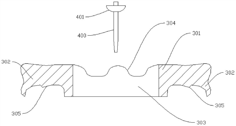
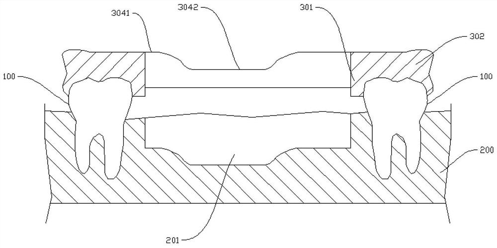
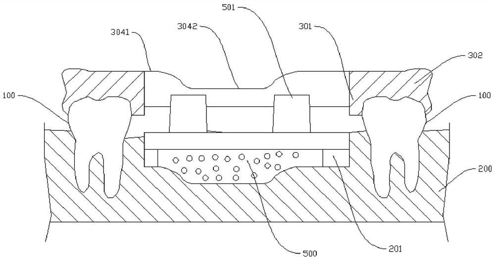
[0025] refer to Figure 1 to Figure 3 The dental implant guide plate assembly shown includes a main body 301 and two fixing parts 302 arranged on both sides of the main body 301. The two fixing parts 302 can be fixedly installed between two adjacent teeth 100, and at this time the main body 301 Located on the part of the alveolar bone 200 to be grooved, the main body 301 is provided with a slotted hole 303, the milling cutter 400 can pass through the slotted hole 303 and mill the implant groove 201 on the alveolar bone 200, specifically, the patient If one or two consecutive teeth 100 are missing ...


PUM


Abstract

The invention relates to the technical field of oral implantation, in particular to an implant tooth guide plate assembly and an implantation grooving method. The implant tooth guide plate assembly comprises a main body and fixing parts; a grooved hole is formed in the main body, and a milling cutter can penetrate through the grooved hole and mill a groove in an alveolar bone; the fixing parts are arranged on two sides of the main body and are used for fixedly mounting the main body in an area between two adjacent teeth; and the main body is positioned on a to-be-grooved part of the alveolar bone. According to the implant tooth guide plate assembly, the fixing parts are arranged on the two sides of the main body, the main body is fixedly installed in the area between the two adjacent teeth in the oral cavity through the fixing parts, the grooved hole is formed in the main body, and the milling cutter can penetrate through the grooved hole and mill the groove in the alveolar bone, so that the technical blank that no guide plate matched with the milling cutter exists in the industry is filled; and the groove depth of the groove milling can be limited through the upper end face of the main body, the milling position and the milling depth of the milling cutter are strictly controlled, and nerve blood vessel bundles or normal tooth roots on the alveolar bone are prevented from being accidentally injured due to manual operation.

Description

technical field [0001] The invention relates to the technical field of oral implantation, in particular to an implant guide plate assembly and an implant slotting method. Background technique [0002] Modern dental implant technology has developed into an independent research category in mature stomatology supported by multi-disciplinary cutting-edge technologies, and has established a more scientific, more reasonable and more complete new concept and method. Compared with traditional dentures, the load of implants is transferred to the surrounding biological tissues, which has significant advantages, so dental implants have developed rapidly in recent years. At present, the chewing function of dental implants is superior to that of traditional dentures. Its advantages such as good implant stability, aesthetics and comfort, and one-time implantation have become the first choice for patients with missing teeth or tooth plastic surgery. [0003] Dental implant surgery usually...

Claims


Application Information

Patent Timeline
IPC IPC(8): A61C8/00
CPCA61C8/009A61C8/0089
Inventor 乔栒柏
Owner 珠海乔丹科技股份有限公司
Learn More