Air curtain cover of laser cutting equipment

A laser cutting and equipment technology, applied in laser welding equipment, welding equipment, metal processing equipment, etc., can solve the problems of dragging the laser head, high cost, and high energy consumption, so as to avoid component fatigue, reduce energy consumption, and work reliable effect

Pending Publication Date: 2022-01-14
江苏觅科激光设备有限公司
View PDF9 Cites 0 Cited by
  • Summary
  • Abstract
  • Description
  • Claims
  • Application Information

AI Technical Summary

Problems solved by technology

The first type is the long strip shape of the dust collection cover, which is arranged on the beam body as a whole; when the laser head moves on the beam body for processing, the dust collector connected to the dust collection cover is opened to carry out suction and dust removal; the volume of this dust collection cover Larger, the part that is not laser cut is also vacuumed during vacuuming, and the energy consumption required for vacuuming is relatively large
The second one is that the dust cover is fixed with the laser head, so that the dust cover can move with the laser head; however, since the dust cover is heavy and in the state of suction, it is easy to generate vibration, so this connection will drag the laser head, affecting the accuracy of laser head movement
[0006] The above technology uses multiple sensors to control the opening and closing of the dust suction pipe. Although it realizes the suction and dust removal at a fixed point, it uses multiple sensors and multiple dust suction pipe opening and closing valves. This electromechanical combination technology, the structure Too complicated and expensive

Method used


Image

  • Air curtain cover of laser cutting equipment
  • Air curtain cover of laser cutting equipment

Examples


Embodiment Construction

[0021] Next, the technical solutions in the embodiments of the present invention will be described in connection with the drawings of the embodiments of the present invention, and it is understood that the described embodiments are merely the embodiments of the present invention, not all of the embodiments. Based on the embodiments of the present invention, all other embodiments obtained by those of ordinary skill in the art are in the range of the present invention without making creative labor premise.

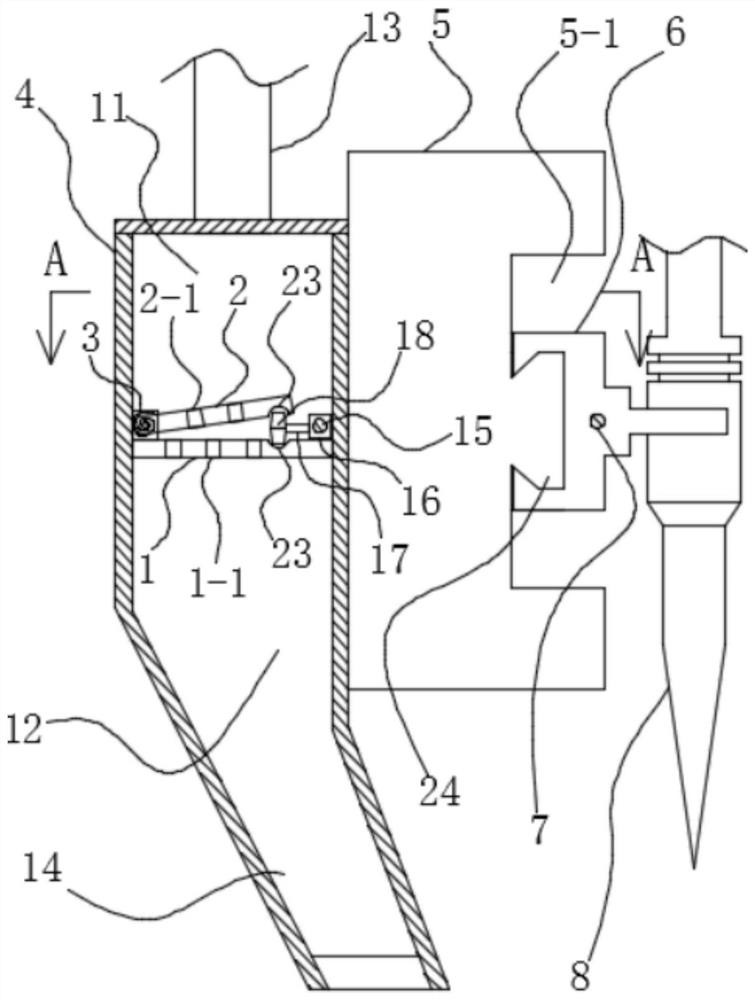
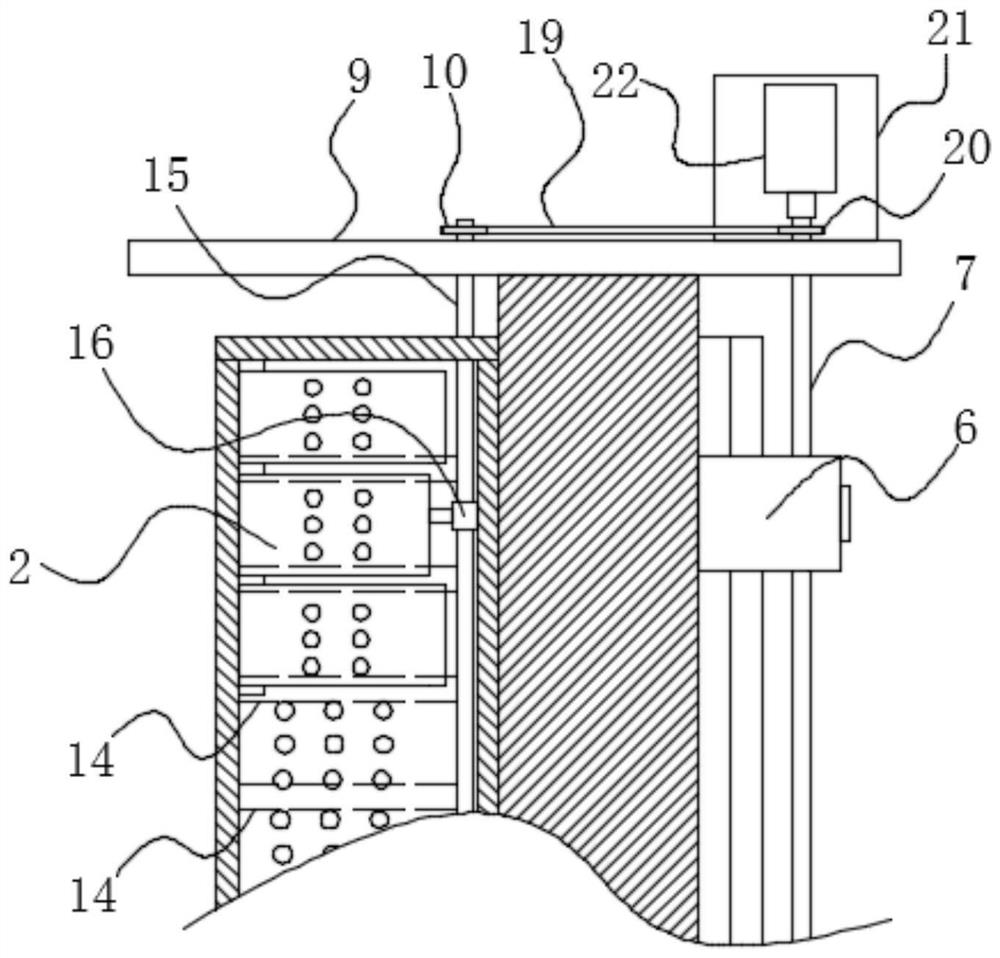
[0022] like figure 1 and figure 2 As shown, the branch plate 9 is fixed to both ends of the tap 5, and the groove 5-1 is opened on the side surface of the stringer 5-1, and the groove 5-1 has a tail slide rail 24. The connecting seat 6 is located in the recess 5-1 of the tap 11, and the connecting seat 6 is slidable with the rail 24. The connecting seat 6 extends extends having a mount 6-1, the connecting seat 6, and the mount 6-1 are integrally formed, and the laser head 8 is c...


PUM


Abstract

The invention discloses an air curtain cover of laser cutting equipment, and belongs to the technical field of laser cutting machining. The air curtain cover comprises a longitudinal beam and a connecting base, a long smoke hood is connected to one side of the longitudinal beam, and a driving screw rod is installed on the connecting base through threaded connection; a sealing plate is fixed in the smoke hood, the upper side of the sealing plate is a sealed negative pressure cavity, and the lower side of the sealing plate is an air suction cavity; a plurality of partition plates are fixed in the air suction cavity; a row of cover plates are hinged to the sealing plate, and torsional springs are installed on hinge shafts of the cover plates and the sealing plate; a driven screw rod is arranged in the smoke hood in a penetrating manner and linked with the driving screw rod; and a sliding block is installed on the driven screw rod in a threaded connection mode, a small shaft is fixed to the sliding block, and a shuttle block is fixed to the end of the small shaft and located between the cover plates and the sealing plate. According to the air curtain cover, the driven screw rod is linked with the driving screw rod, so that the shuttle block always corresponds to a laser head in position; and the shuttle block moves to open the corresponding cover plates, then the independent cavity which is closest to the laser head and used for air suction is opened, and fixed-point dust collection is only carried out on a cutting part.

Description

Technical field [0001] The present invention relates to the field of laser cutting processing, and is specifically a laser cutting device. Background technique [0002] The laser processing equipment is a laser beam heating workpiece using high energy density, which has rapidly rises rapidly, and reaches the boiling point of the material in a very short period of time, and the material begins to vaporize. The spray speed of these vapors is very large, and the slit is formed on the material while the vapor is ejected. The laser processing equipment produces a large smoke when the cloth or leather product, will exude a harmful gas, which affect the health of the operator, so the laser cutting machine will generally be provided with a dust cover. [0003] Existing dust covers generally have two arrangements. The first, the dust cover is long, and the whole is arranged on the beam; when the laser head is moved on the beam body, the dust collector connected to the dust cover is opened...

Claims


Application Information

Patent Timeline
IPC IPC(8): B23K26/16B23K26/38
CPCB23K26/16B23K26/38
Inventor 王世伟马加飞穆浩
Owner 江苏觅科激光设备有限公司
Why Eureka
Try Eureka