Pipe fitting positioning device and equipment for machining pipe fitting

A technology of positioning device and positioning assembly, applied in the field of pipe fitting processing, can solve the problems of cumbersome operation, low work efficiency, hindering processing procedures, etc., and achieve the effects of increasing processing area, compact overall structure, and improving work efficiency

Active Publication Date: 2022-01-14
SHANDONG SENTER ELECTRONICS
View PDF8 Cites 1 Cited by
  • Summary
  • Abstract
  • Description
  • Claims
  • Application Information

AI Technical Summary

Problems solved by technology

Most of the pipe fitting fixtures in the related art clamp the outer wall of the pipe fitting. This method not only occupies the area of ​​the outer wall of the pipe fitting and reduces the effective processing area of ​​the outer wall of the pipe fitting, but also may interfere with the equipment or device for processing the pipe fitting, hindering the smooth progress of the processing procedure. ; Moreover, for thin-walled pipe fittings, the pipe fittings are easily squeezed and deformed during clamping, making it difficult to grasp the clamping stability and clamping accuracy of such parts
In addition, some pipe fixtures can only clamp fixed size pipes, lacking versatility and flexibility
There are also some pipe fitting fixtures that are cumbersome to operate, which is not conducive to the installation or removal of pipe fittings, resulting in low work efficiency

Method used


Image

  • Pipe fitting positioning device and equipment for machining pipe fitting
  • Pipe fitting positioning device and equipment for machining pipe fitting
  • Pipe fitting positioning device and equipment for machining pipe fitting

Examples


Embodiment Construction

[0035] In order to explain the overall concept of the present application more clearly, the following detailed description will be given by way of examples in conjunction with the accompanying drawings.

[0036]In the following description, many specific details are set forth in order to fully understand the application, but the application can also be implemented in other ways different from those described here, therefore, the protection scope of the application is not limited by the specific details disclosed below. EXAMPLE LIMITATIONS. It should be noted that, in the case of no conflict, the embodiments of the present application and features in each embodiment may be combined with each other.

[0037] In addition, in the description of the present application, it should be understood that the orientation or positional relationship indicated by the terms "inner", "outer", "axial", "radial", and "circumferential" are based on the The orientation or positional relationship ...


PUM


Abstract

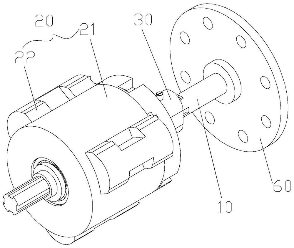
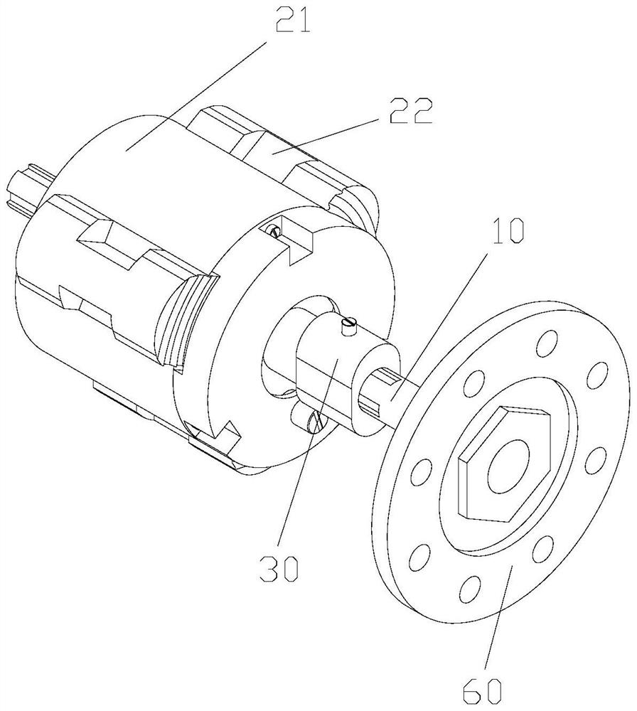
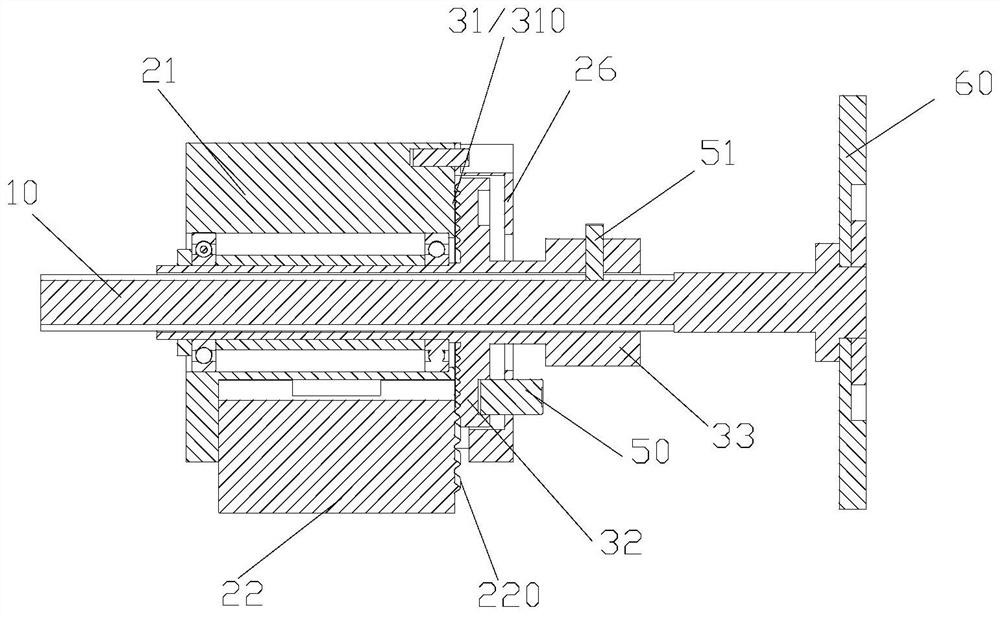
The invention discloses a pipe fitting positioning device. The pipe fitting positioning device comprises a supporting rod, a positioning assembly and a driving part; the positioning assembly is arranged on the supporting rod in a sleeving mode, the positioning assembly can stretch into the pipe fitting, the positioning assembly comprises a fixed part and at least two movable parts arranged in the circumferential direction of the fixed part, the fixed part is provided with a sliding way in the radial direction of the supporting rod, and the movable parts are in sliding fit with the sliding way; and the driving part is arranged on the supporting rod in a sleeving mode and connected with the fixed part, a driving part is arranged at the side, facing the movable parts, of the driving part, and when the driving part rotates around the supporting rod, the driving part drives the movable parts to move along the sliding way so that the movable part can have a first state of tightly supporting the pipe fitting from the interior of the pipe fitting and a second state of being separated from the inner wall of the pipe fitting. According to the pipe fitting positioning device, the pipe fitting can be tensioned and supported from the interior of the pipe fitting, and the machined area of a pipe workpiece can be effectively increased; and the positioning device can be used for operating the pipe workpiece with a wide pipe diameter range, and has high operation flexibility and adaptability.

Description

technical field [0001] The application belongs to the technical field of pipe fittings processing, and in particular relates to a pipe fitting positioning device and equipment for processing pipe fittings. Background technique [0002] In the field of pipe fittings processing, it is usually necessary to fix or position the pipe fittings first, and then process, process or inspect them. Most of the pipe fitting fixtures in the related art clamp the outer wall of the pipe fitting. This method not only occupies the area of ​​the outer wall of the pipe fitting and reduces the effective processing area of ​​the outer wall of the pipe fitting, but also may interfere with the equipment or device for processing the pipe fitting, hindering the smooth progress of the processing procedure. ; Moreover, for thin-walled pipe fittings, the pipe fittings are easily squeezed and deformed during clamping, making it difficult to grasp the clamping stability and clamping accuracy of such parts....

Claims


Application Information

Patent Timeline
Patent Type & Authority Applications(China)
IPC IPC(8): B23Q3/00B23Q3/18B24B41/06
CPCB23Q3/00B23Q3/18B24B41/067B23Q2703/10
Inventor 许辉蔡富东孔志强陈雷杨玉国马海峰耿玉杰
Owner SHANDONG SENTER ELECTRONICS
Why Eureka
Try Eureka