Chuck device for vertical ampoule making machine applied to powder coating production

A technology of powder coating and ampoules, which is applied in the direction of manufacturing tools, glass manufacturing equipment, glass reshaping, etc., can solve the problem of ampoules falling, and achieve the effect of avoiding deformation

Inactive Publication Date: 2022-02-01
HUNAN LIANXIN SCI & TECH CO LTD
View PDF0 Cites 0 Cited by
  • Summary
  • Abstract
  • Description
  • Claims
  • Application Information

AI Technical Summary

Problems solved by technology

[0006] The invention provides a chuck device for a vertical ampoule making machine for powder coating production, which solves the problem that the ampoule needs to collide with a collision block to make the ampoule drop

Method used


Image

  • Chuck device for vertical ampoule making machine applied to powder coating production
  • Chuck device for vertical ampoule making machine applied to powder coating production
  • Chuck device for vertical ampoule making machine applied to powder coating production

Examples


no. 1 example

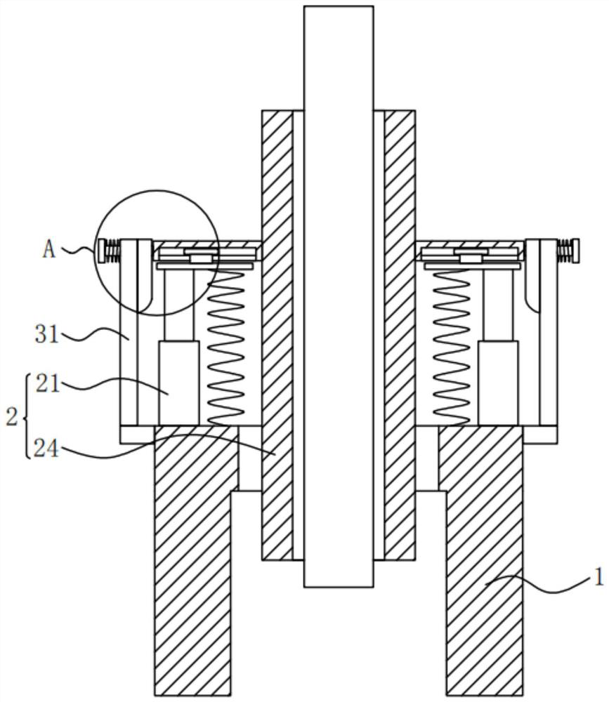
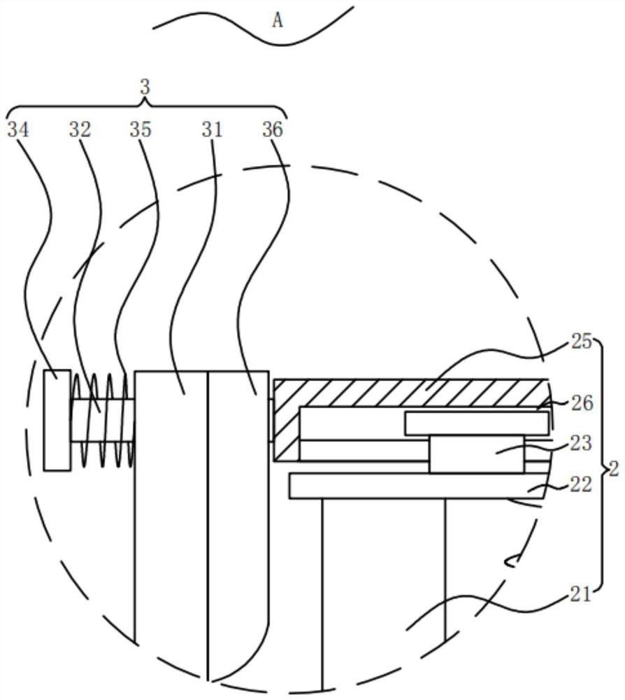
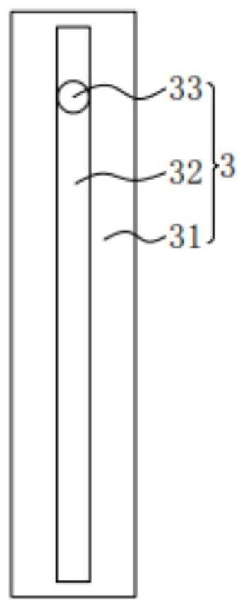
[0025] Please refer to figure 1 , figure 2 , image 3 ,in, figure 1 The structural representation of the first embodiment of the chuck device for the powder coating production vertical ampoule bottle making machine provided by the present invention; figure 2 for figure 1 The enlarged schematic diagram of part A shown; image 3 for figure 1 Side view of the L-shaped plate shown. A chuck device for a vertical ampoule bottle-making machine for powder coating production includes: a base 1; a lifting assembly 2, the lifting assembly 2 is fixed on the base 1, the lifting assembly 2 includes a cylinder 21, The output end of the cylinder 21 is fixedly connected with a connecting plate 22, the connecting plate is fixedly connected with a convex block 23, the inside of the base 1 is slidably connected with a clamping plate 24, and the clamping plate 24 is fixedly connected There is a push plate 25, the interior of the push plate 25 is provided with a convex groove 26; a sliding...

no. 2 example

[0040] see image 3 , Figure 4 , Figure 5 , based on the chuck device for a vertical ampoule-making machine for powder coating production provided in the first embodiment of the application, the second embodiment of the application proposes another vertical ampoule-making machine for powder coating production Chuck device. The second embodiment is only a preferred mode of the first embodiment, and the implementation of the second embodiment will not affect the independent implementation of the first embodiment.

[0041] Specifically, the difference between the chuck device for the vertical ampoule-making machine for powder coating production provided by the second embodiment of the present application is that the chuck device for the vertical ampoule-making machine for powder coating production also includes: Pushing assembly 4, described pushing assembly 4 is fixed on described base 1, and described pushing assembly 4 comprises motor 41, and the output end of described mot...


PUM


Abstract

The invention provides a chuck device for a vertical ampoule making machine applied to powder coating production. The chuck device comprises: a base; a lifting assembly, which is fixed to the base and comprises an air cylinder, wherein the output end of the air cylinder is fixedly connected with a connecting plate, the connecting plate is fixedly connected with a convex block, the interior of the base is slidably connected with a clamping plate, the clamping plate is fixedly connected with a pushing plate, and a convex groove is formed in the pushing plate; and a sliding assembly, wherein the sliding assembly is fixed to the base, the sliding assembly comprises an L-shaped plate, and a sliding groove is formed in the L-shaped plate. According to the chuck device for the vertical ampoule making machine applied to powder coating production, after an ampoule is driven by an air cylinder to move downwards by a moving distance, the ampoule is not clamped by the clamping plate any more, so the ampoule is allowed to fall off, and the situation that deformation of the ampoule is easily caused as the ampoule falls off under collision with external force, and consequently the qualified rate of ampoule machining is reduced and raw materials for manufacturing the ampoule are wasted is avoided.

Description

technical field [0001] The invention relates to the field of ampoules technology, in particular to a chuck device for a vertical ampoules bottle making machine for powder coating production. Background technique [0002] Powder coating is a solid powder synthetic resin coating composed of solid resin and pigments, fillers and additives. Unlike ordinary solvent-based paints and water-based paints, its dispersion medium is not solvent and water, but air. It has the characteristics of no solvent pollution, 100% film formation and low energy consumption. There are two types of powder coatings, thermoplastic and thermosetting. Thermoplastic powder coatings have poor film appearance (gloss and leveling) and poor adhesion to metals, so they are rarely used in the field of automotive coatings. Thermosetting powder coatings are generally used in automotive coatings, and thermosetting powder coatings are The thermosetting synthetic resin is used as the film-forming substance. Durin...

Claims


Application Information

Patent Timeline
Patent Type & Authority Applications(China)
IPC IPC(8): C03B23/045
CPCC03B23/045
Inventor 夏连心杨立兵朱满子方志旺
Owner HUNAN LIANXIN SCI & TECH CO LTD
Why Eureka
Try Eureka