Numerical control grinding track calculation method for peripheral tooth chip separating groove of rough milling cutter

A technology of chip splitter and rough milling cutter, applied in milling cutter, milling machine equipment, comprehensive factory control, etc., to achieve the effect of strong flexibility, good processing adaptability and high calculation accuracy

Active Publication Date: 2022-01-14
SOUTHWEST JIAOTONG UNIV +1
View PDF5 Cites 8 Cited by
  • Summary
  • Abstract
  • Description
  • Claims
  • Application Information

AI Technical Summary

Problems solved by technology

For the machining of peripheral tooth chip splitters, there is no complete and open parametric definition and parametric NC grinding trajectory algorithm.

Method used


Image

  • Numerical control grinding track calculation method for peripheral tooth chip separating groove of rough milling cutter
  • Numerical control grinding track calculation method for peripheral tooth chip separating groove of rough milling cutter
  • Numerical control grinding track calculation method for peripheral tooth chip separating groove of rough milling cutter

Examples


Embodiment Construction

[0067] The present invention will be described in further detail below in conjunction with the accompanying drawings and specific implementation examples.

[0068] A numerical control grinding trajectory calculation method of a peripheral tooth chip groove of a rough milling cutter according to the present invention comprises the following steps:

[0069] Step 1: Define the coordinate system and transformation.

[0070] Workpiece coordinate system:

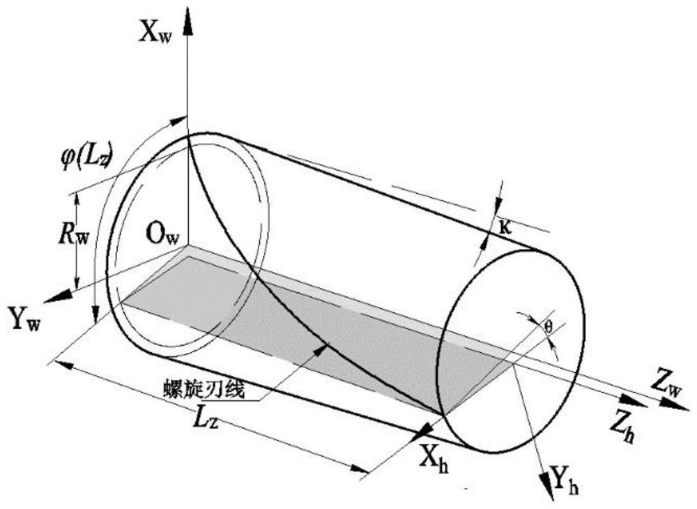
[0071] Define the workpiece coordinate system O w -X w Y w Z w Such as figure 1 As shown, its origin O w Located on the tool axis, coordinate axis Z w Coincident with the tool axis, the starting point of the helical edge of the peripheral tooth is at X w Y w In the plane and intersecting with the coordinate axis X w positive direction. In this paper, the description of the grinding wheel's grinding pose is based on the workpiece coordinate system.

[0072] Rear corner coordinate system:

[0073] Define the rear corner...


PUM


Abstract

The invention discloses a numerical control grinding track calculation method for a peripheral tooth chip separating groove of a rough milling cutter. The numerical control grinding track calculation method specifically comprises the following steps: firstly, defining structural parameters of the peripheral tooth chip separating groove of the rough milling cutter, and establishing a machining coordinate system and a cutting depth guide curve equation; and secondly, by means of the kinematics theory, providing a calculation method for the grinding wheel grinding posture and the grinding wheel grinding track. A chip flute structure is flexibly machined by controlling the moving posture of a grinding wheel, and good cutter structure expansibility and machining precision are achieved.

Description

technical field [0001] The invention belongs to the technical field of end mill structure design, and in particular relates to a numerical control grinding trajectory calculation method of a peripheral tooth chip groove of a rough milling cutter. Background technique [0002] In the rough machining milling stage, the consideration of material removal rate is always prioritized over parameters such as machining accuracy [Matsumura, Takashi, Eiji USUI. Analysis of Cutting Process with Roughing EndMill [J]. International Journal of Material Forming, 2009, 2( 1):555-558.]. For N-edge milling tools, the cutting thickness of milling cutters with chip splitter structure can be up to N times that of milling cutters with continuous linear cutting edges, and have lower cutting constants and cutting energy savings of up to 23%[ J.-J.Junz Wang,C.S.Yang.Angle and frequency domain force models for through end mill with a sinusoidal edge profile[J].International journal of machine tools&m...

Claims


Application Information

Patent Timeline
Patent Type & Authority Applications(China)
IPC IPC(8): B24B1/00B24B3/02
CPCB24B1/00B24B3/02Y02P90/02
Inventor 江磊丁国富李海宾张剑马术文丁国华
Owner SOUTHWEST JIAOTONG UNIV
Why Eureka
Try Eureka