Semi-automatic corrugated beam guardrail plate mounting machine and working method thereof

A wave beam guardrail, panel installation machine technology, applied in road safety devices, roads, buildings, etc., can solve the troublesome problems of guardrail panels, and achieve the effect of easy transportation

Pending Publication Date: 2022-01-14
聊城市交通发展有限公司
View PDF8 Cites 2 Cited by
  • Summary
  • Abstract
  • Description
  • Claims
  • Application Information

AI Technical Summary

Problems solved by technology

[0005] In order to improve the troublesome problem of installing guardrail boards with hooks, this application provides a semi-automatic corrugated beam guardrail board installation machine and its working method

Method used


Image

  • Semi-automatic corrugated beam guardrail plate mounting machine and working method thereof
  • Semi-automatic corrugated beam guardrail plate mounting machine and working method thereof
  • Semi-automatic corrugated beam guardrail plate mounting machine and working method thereof

Examples


Embodiment 1

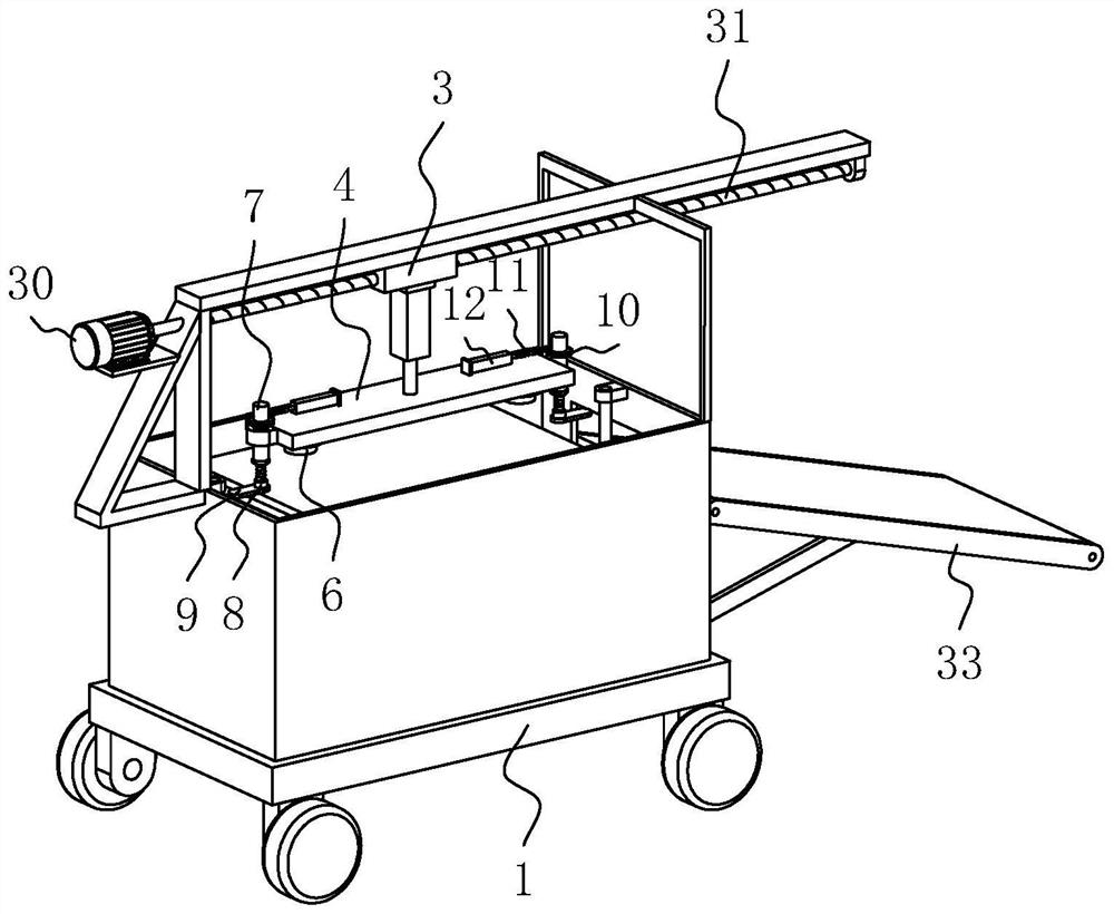
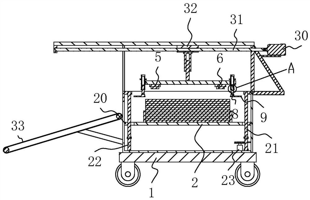
[0042] The embodiment of the present application discloses a semi-automatic corrugated beam guardrail board installation machine and its working method. refer to figure 1 A semi-automatic corrugated beam guardrail panel installation machine and its working method include a delivery vehicle 1, a storage mechanism installed in the delivery vehicle 1, and a transmission mechanism for transmitting the guardrail panel. The transmission mechanism is also located in the delivery vehicle 1, and the transmission mechanism adopts The conveyor belt 33 connected with the delivery car 1 transmission, the conveyor belt 33 is inclined, and the conveyor belt 33 is driven by the driving roller and the driven roller that are connected to the delivery vehicle 1 in rotation. After the guardrail is transported to the conveyor belt 33, the conveyor belt 33 will The guardrail is transported to the location to be processed.

[0043] refer to figure 1 and figure 2 , the storage mechanism includes ...

Embodiment 2

[0057] The embodiment of the present application discloses a working method of a semi-automatic wave beam guardrail installation machine. refer to figure 1 A working method of a semi-automatic corrugated beam guardrail panel installation machine comprises the following steps,

[0058] S1, preparatory work, pile up guardrail plate on storage board 2 in sequence;

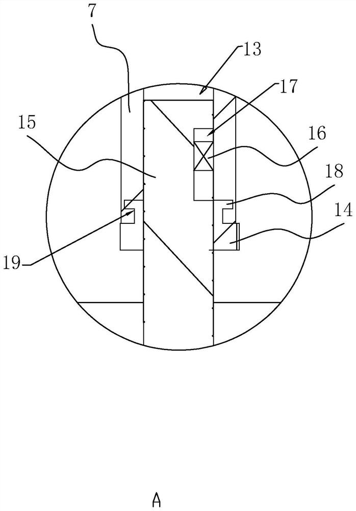
[0059]S2. Adjust the position of the support block 9, drive the nut 14 to rotate, and the screw rod 15 moves together. Under the action of the relative movement between the limit block 16 and the limit groove 17, the screw rod 15 drives the lifting rod 8 to slide in the rotation rod 7 Movement in the hole 13, and then realize the adjustment effect to the position of the support block 9, the distance between the bottom surface of the control electromagnet 6 and the top surface of the support block 9 is equal to the thickness of the guardrail plate;

[0060] S3, the electromagnet 6 is adsorbed, the first oil cylinder ...


PUM


Abstract

The invention relates to a semi-automatic corrugated beam guardrail plate mounting machine and a working method thereof and relates to the field of guardrail equipment mounting. The semi-automatic corrugated beam guardrail plate mounting machine comprises a putting vehicle, and a storage mechanism and a conveying mechanism which are arranged in the putting vehicle; the storage mechanism comprises a storage plate arranged in the putting vehicle in a lifting mode, a support connected to the interior of the putting vehicle in a sliding mode and a lifting plate arranged on the support in a lifting mode, the putting vehicle is provided with a power assembly, the lifting plate is provided with a plurality of lifting blocks, and the lifting blocks are provided with electromagnets used for adsorbing guardrail plates; the lifting plate is rotationally connected with a rotating rod, the rotating rod is provided with a lifting rod in a lifting mode, an end, away from the rotating rod, of the lifting rod is fixedly connected with a supporting block, and the lifting plate is provided with a driving assembly. The machine is advantaged in that the guardrail plate is convenient to take and place, the whole process is high in active degree, and labor intensity of workers is greatly reduced.

Description

technical field [0001] The application relates to the field of guardrail installation equipment, in particular to a semi-automatic waveform beam guardrail panel installation machine and its working method. Background technique [0002] At present, the corrugated guardrail is a kind of highway anti-collision facility, which is composed of two corrugated beam steel guardrail panels and two guardrail columns fixedly placed between them. Different specifications are adopted. At present, the installation of wave beam guardrail panels still adopts the traditional method of manually transporting the guardrail panels to the position of the columns and then installing them. At least two workers are required to cooperate with the installation during installation. This installation method cannot be carried out. Continuous operation, the overall work efficiency is low. [0003] The existing patent announcement number is CN201810735592.X, which proposes a semi-automatic wave beam guardr...

Claims


Application Information

Patent Timeline
Patent Type & Authority Applications(China)
IPC IPC(8): E01F15/04
CPCE01F15/0484
Inventor 张忠周斌徐大军丁敬荣徐光冯吉利
Owner 聊城市交通发展有限公司
Why Eureka
Try Eureka