
Hoisting method for large-span steel structure of limited working face in heating furnace area

A hoisting method and heating furnace technology, which are applied in building structure, building material processing, construction and other directions, can solve the problems that cranes cannot be hoisted, the construction site cannot be hoisted in place at one time, and the hoisting environment in the heating furnace area is complex, etc. The effect of hoisting construction progress, improving construction efficiency and saving construction costs

Pending Publication Date: 2022-01-14
SHANGHAI BAOYE GRP CORP
View PDF2 Cites 0 Cited by
  • Summary
  • Abstract
  • Description
  • Claims
  • Application Information

AI Technical Summary

Problems solved by technology

[0002] The diameter of the steel flue in the heating furnace area is 3520mm and it belongs to the lower row type flue. It is located in a narrow and long concrete passage between the preheater of the heating furnace and the chimney. There is a roof on the upper part of the passage. The clear height of the passage is 9.7m and the clear width of the passage 5.6m~6.35m, it cannot be directly hoisted in place by traditional methods such as driving or car crane
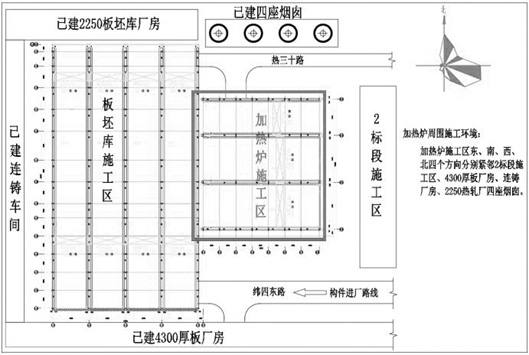
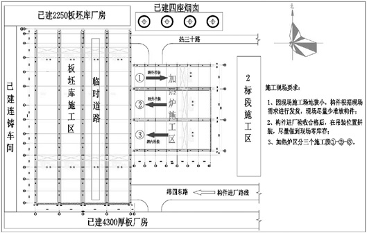
[0003] Furthermore, the hoisting environment in the heating furnace area is complicated. After the excavation of the deep foundation pit on the south side, the slope top line is about 43m away from the center line of the 39m long-span steel column. The distance is too far for the crane to hoist. There is no crane station on the west side due to the interference of the construction area of ​​the second bid section The construction site on the west and north sides is too narrow to be hoisted in place at one time, and the 39m long-span single-piece H-shaped solid composite steel roof beam in the heating furnace area weighs about 9.5t, and the hoisting height is about 24.16m

Method used


Image

  • Hoisting method for large-span steel structure of limited working face in heating furnace area
  • Hoisting method for large-span steel structure of limited working face in heating furnace area
  • Hoisting method for large-span steel structure of limited working face in heating furnace area

Examples


Embodiment Construction

[0029] The present invention is further illustrated below by specific examples.

[0030] Such as Figure 1~Figure 8 As shown, a hoisting method for a large-span steel structure with a restricted working surface in the heating furnace area, including

[0031] Step (1) Understand the construction environment: understand the construction status in the east, south, west and north directions of the heating furnace area, the distribution of existing buildings, roads and aerial work surfaces;

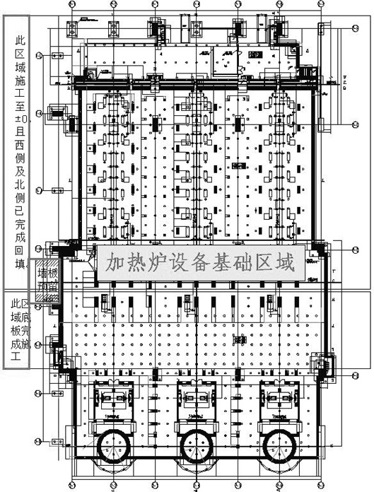
[0032] Step (2) The construction conditions are reserved in advance for the hoisting of the steel structure during the preliminary construction: when the roof beams of the heating furnace are hoisted, the equipment foundation of the heating furnace has been constructed to ±0, and the strength of the bottom plate and column foundation has reached the design strength, ensuring that the heating The earthwork backfilling on the northwestern sides adjacent to the furnace has been completed, which ...


PUM


Abstract

The invention relates to the technical field of construction of metallurgical plants, and particularly relates to a hoisting method for a large-span steel structure of a limited working face in a heating furnace area. The hoisting method comprises the steps that (1) the construction environment is known; (2) construction conditions are reserved for steel structure hoisting in advance during early-stage construction; (3) the hoisting sequence design is determined; (4) the construction process design is conducted; and (5) crane type selection and station design are conducted. According to the hoisting method, starting from the actual situation that large-span steel structure hoisting is affected by the surrounding environment, overall planning and layout are conducted on the aspects of the hoisting sequence, the public process, crane type selection and station, accordingly, the limitation of the limited space of the heating furnace area to hoisting of large components such as large-span roof beams and large-diameter circular pipe flues is broken through, the hoisting construction progress of the large components in the limited space is greatly accelerated, the construction efficiency is improved, and the construction cost is saved.

Description

technical field [0001] The invention relates to the technical field of construction of metallurgical workshops, in particular to a hoisting method for a large-span steel structure on a restricted working surface in a heating furnace area. Background technique [0002] The diameter of the steel flue in the heating furnace area is 3520mm and it belongs to the lower row type flue. It is located in a narrow and long concrete passage between the preheater of the heating furnace and the chimney. There is a roof on the upper part of the passage. The clear height of the passage is 9.7m and the clear width of the passage 5.6m~6.35m, it cannot be directly hoisted in place by traditional methods such as driving or car crane. [0003] Furthermore, the hoisting environment in the heating furnace area is complicated. After the excavation of the deep foundation pit on the south side, the slope top line is about 43m away from the center line of the 39m long-span steel column. The distance i...

Claims


Application Information

Patent Timeline
IPC IPC(8): E04G21/14E04G21/00
CPCE04G21/14E04G21/00
Inventor 杨国强吴爱成张啸风宋茂祥沈汉兵李大伟
Owner SHANGHAI BAOYE GRP CORP
Learn More