
On-orbit correction and deformation evaluation method for phased-array antenna

A phased array antenna and array antenna technology, applied in antenna, genetic law, special data processing application, etc., can solve the problem of increasing satellite load design cost and system complexity, limited installation accuracy of measurement equipment, and inability to meet the weight of satellite platform Limiting requirements and other issues to achieve the effect of reducing the cost of satellite loads, facilitating engineering realization, and facilitating system weight reduction

Pending Publication Date: 2022-01-14
XIAN INSTITUE OF SPACE RADIO TECH
View PDF0 Cites 2 Cited by
  • Summary
  • Abstract
  • Description
  • Claims
  • Application Information

AI Technical Summary

Problems solved by technology

These measurement and correction systems can realize real-time monitoring and correction of errors, but are largely limited by the installation accuracy of the measurement equipment, and at the same time increase the design cost and system complexity of the satellite load, often unable to meet the weight limit requirements of the satellite platform

Method used


Image

  • On-orbit correction and deformation evaluation method for phased-array antenna
  • On-orbit correction and deformation evaluation method for phased-array antenna
  • On-orbit correction and deformation evaluation method for phased-array antenna

Examples


Embodiment Construction

[0055] The present invention will be further elaborated below in conjunction with embodiment.

[0056] In order to realize phased array on-orbit correction and deformation evaluation, the specific calculation steps of the present invention are as follows:

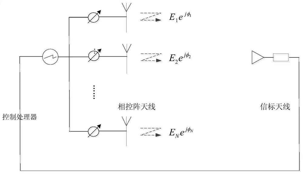
[0057] (1) Referring to the configuration scheme of the external calibration system, the array antenna beacon, passive array and active channel are used to construct an integrated calibration link. The beacon erection meets a certain height and coverage. The system composition is as follows figure 1 shown.

[0058] (2) Use photogrammetry and other high-precision structural measurement methods to complete the radiation front surface accuracy correction and mechanical structure measurement on the ground and record Form A1.

[0059] (3) Use methods such as REV (rotation vector method) to complete the active channel trim and amplitude-phase consistency check in the darkroom on the ground, and record the tables as A2 and A3 res...


PUM


Abstract

The invention relates to an on-orbit correction and deformation evaluation method for a phased-array antenna. The method comprises the following steps: firstly, carrying out ground structure and amplitude-phase measurement on an integrated link of a beacon, an array plane and a channel of the active phased-array antenna; then obtaining on-orbit compensation phases of all channels through calculation on the basis of ground amplitude-phase measurement data, and on-orbit correction of the electrical performance of the phased-array antenna is completed; secondly, according to the phase change value of each channel, obtaining the physical deformation length from the array antenna beacon to the position of each array plane unit; comparing and calculating with the measured data of the ground structure of the array antenna, and predicting the possible position coordinates of each unit of the array plane after in-orbit deformation; and finally, attributing the array surface deformation on-orbit evaluation to the optimization problem of the array surface unit position, constructing a deformation optimization model and optimization constraint conditions to update the array element position, solving the final array element position coordinate on the basis of multiple iterative optimization, and realizing the on-orbit profile change evaluation.

Description

technical field [0001] The invention relates to an on-orbit correction and deformation evaluation method of a phased array antenna, which belongs to the field of spaceborne array antenna design. Background technique [0002] Spaceborne SAR (Synthetic Aperture Radar) active phased array antenna has the characteristics of high gain, narrow beam, fast beam scanning and beam shape agility, which can meet the performance requirements of spaceborne electronic information equipment. The new spaceborne SAR phased array antenna has a large diameter, a large number of boards, large external temperature changes, and large heat consumption of the boards. The array has requirements for flexibility and light weight. The truss method is used to achieve reliable deployment and meet the high precision of the antenna profile. Require. Affected by factors such as the space environment and other factors, the shape of the spaceborne array antenna may change in orbit, such as the thermal deforma...

Claims


Application Information

Patent Timeline
Patent Type & Authority Applications(China)
IPC IPC(8): G06F17/10G06F30/17G06F30/27G06N3/12H01Q3/34
CPCG06F17/10G06F30/17G06F30/27G06N3/126H01Q3/34
Inventor 赵宏伟吴疆李琳王迪瞿颜李成国李樊
Owner XIAN INSTITUE OF SPACE RADIO TECH
Learn More