Unit module and battery pack
A unit module and battery pack technology, applied in secondary batteries, battery pack components, circuits, etc., can solve the indeterminate position of the thermal runaway of soft pack cells, unfavorable thermal runaway protection measures for battery packs, and hidden dangers of battery pack safety, etc. To reduce the risk of thermal runaway, alleviate heat concentration, and achieve the effect of reliable heat dissipation
- Summary
- Abstract
- Description
- Claims
- Application Information
AI Technical Summary
Problems solved by technology
Method used
Image
Examples
Embodiment 1
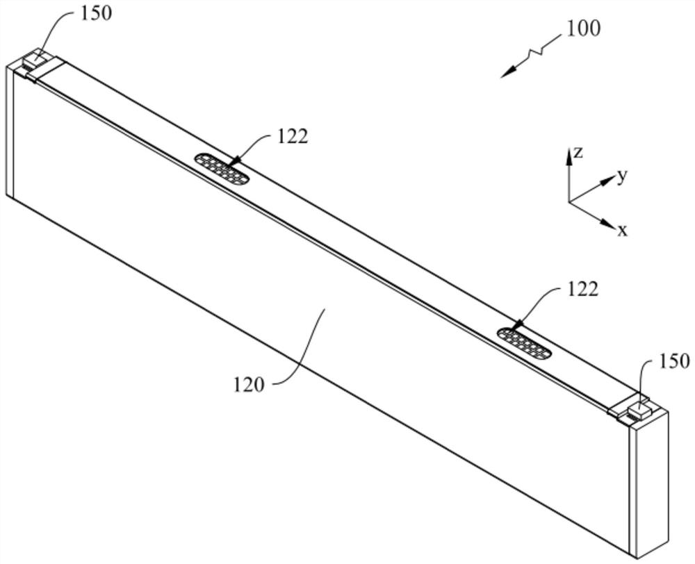
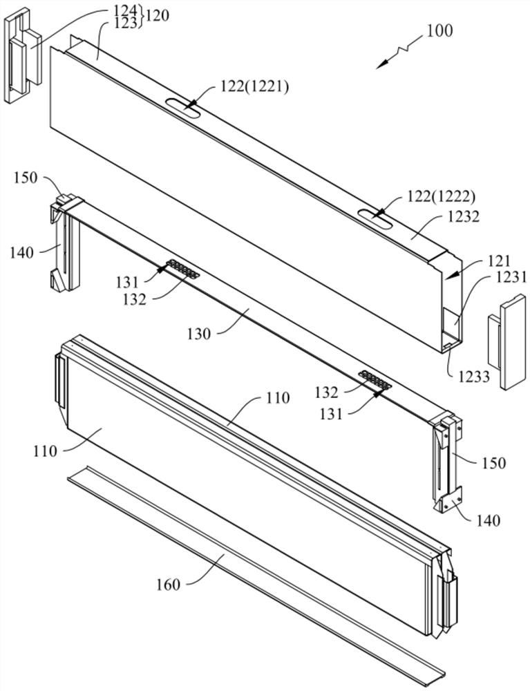
[0054] see figure 1 , figure 2 , the embodiment of the present invention provides a unit module 100, including at least one pouch cell 110 and a housing assembly 120, a housing cavity 121 for accommodating each pouch cell 110 is formed in the housing assembly 120, and the housing assembly 120 is provided with an exhaust hole 122 on one side of the pouch cell 110 in the height direction z to communicate the accommodating cavity 121 to the outside.
[0055] It should be noted here that the housing assembly 120 is a hollow structure, and its interior encloses and forms a receiving cavity 121 , and one or more pouch cells 110 can be accommodated in the receiving cavity 121 . When the accommodation cavity 121 accommodates a plurality of pouch cells 110 , each pouch cell 110 can be stacked along the thickness direction y of the pouch cell 110 , and establish a parallel, series or hybrid power connection relationship.
[0056] Based on this, the casing assembly 120 can protect the...
Embodiment 2
[0096] The difference between this embodiment and Embodiment 1 is:
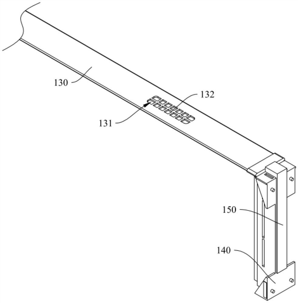
[0097] Please refer to figure 2 , image 3 , in this embodiment, a thin-walled structure (not shown in the figure) that can be broken through is provided in the vent hole 131 .
[0098] By adopting the above scheme, when the pouch cell 110 of the unit module 100 does not experience thermal runaway, the thin-walled structure arranged in the vent hole 131 can be isolated to a certain extent between each pouch cell 110 and the exhaust hole 122 time, so as to form a certain protective and protective effect on each pouch cell 110; and when the pouch cell 110 of the unit module 100 is thermally out of control and reaches a certain pressure, the thin-walled structure arranged in the vent hole 131 can be Break through, and allow the gas and heat exhausted by the pouch cell 110 of thermal runaway to be discharged to the exhaust hole 122 along it. Therefore, by adopting the above scheme, the protection effect of th...
Embodiment 3
[0100] The difference between this embodiment and Embodiment 1 is:
[0101] Please refer to figure 2 , image 3 , in this embodiment, the vent hole 131 is provided with a window structure (not shown in the figure) hinged to the edge of the vent hole 131 .
[0102] By adopting the above scheme, when the pouch cell 110 of the unit module 100 does not experience thermal runaway, the window structure provided in the vent hole 131 can cover the vent hole 131 and be isolated from each pouch cell to a certain extent. 110 and the exhaust hole 122, so as to form a certain protection and protection effect on each pouch cell 110; and when the pouch cell 110 of the unit module 100 undergoes thermal runaway and reaches a certain air pressure, the pouch of the thermal runaway The gas and heat discharged from the battery cell 110 can rush toward the window structure and make the window structure rotate, and then be discharged to the exhaust hole 122 . Therefore, by adopting the above sch...
PUM
 Abstract
Description
Claims
Application Information
 - R&D
- Intellectual Property
- Life Sciences
- Materials
- Tech Scout
- Unparalleled Data Quality
- Higher Quality Content
- 60% Fewer Hallucinations
Browse by: Latest US Patents, China's latest patents, Technical Efficacy Thesaurus, Application Domain, Technology Topic, Popular Technical Reports.
© 2025 PatSnap. All rights reserved.Legal|Privacy policy|Modern Slavery Act Transparency Statement|Sitemap|About US| Contact US: help@patsnap.com


