Easily adjustable examination table for ophthalmology department
A technology of examination table and ophthalmology, which is applied in the field of easy-to-adjust examination table to achieve the effect of smooth movement, convenient ophthalmology examination and stable work
- Summary
- Abstract
- Description
- Claims
- Application Information
AI Technical Summary
Problems solved by technology
Method used
Image
Examples
Embodiment 1
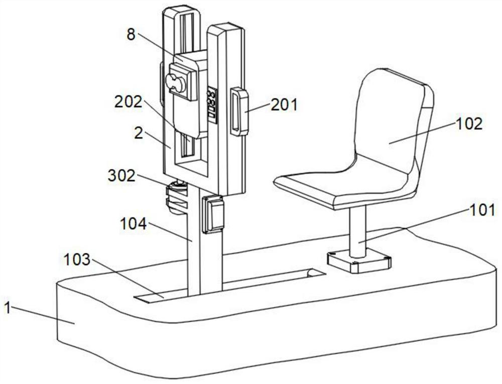
[0033] refer to Figure 1-5 The shown is an easy-to-adjust examination table for ophthalmology, which includes a base 1, a U-shaped base 2 and a visual function tester body 8. A mounting base 101 is fixedly installed on the right side of the upper surface of the base 1, and the end of the mounting base 101 is fixed. A patient seat 102 is installed, and the upper surface of the base 1 is located on the left side of the mounting seat 101, and a chute 103 is provided. The sliding column 104 is installed inside the chute 103 for limit sliding, and the inside of the base 1 is located on both sides of the chute 103. There are buffer components symmetrically arranged , U-shaped seat 2 is fixedly installed on the upper end of sliding column 104, and handles 201 are fixedly installed on both sides of U-shaped seat 2, and guide grooves 202 are provided on the inner wall surfaces at both ends of U-shaped seat 2, and inside the guide groove 202 A lifting assembly is provided, and a visual...
Embodiment 2
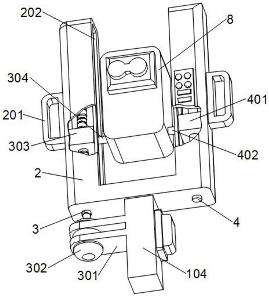
[0036] combine figure 1 and figure 2As shown, based on the above-mentioned embodiment 1, the lifting assembly includes a threaded rod 3 vertically rotatably installed inside the guide groove 202 on one side, and the lower end of the threaded rod 3 penetrates below the U-shaped seat 2, and the sliding column 104 is close to the threaded rod 3 A fixed seat 301 is fixedly installed on the side surface of the fixed seat 301, and a motor 302 is fixedly installed on the end of the fixed seat 301, and the output end of the motor 302 is coaxially fixedly connected with the lower end of the threaded rod 3, and the outer surface of the threaded rod 3 is engaged with a moving block 303 , and the moving block 303 is limited and slidably installed inside the guide groove 202, the outer surface of the moving block 303 is fixed with a fixed rod A304 penetrating to the outside of the guide groove 202, and the end of the fixed rod A304 is fixedly connected to the side surface of the visual fu...
Embodiment 3
[0038] combine figure 2 As shown, based on the above-mentioned embodiment 1 or 2, the inside of the guide groove 202 opposite to the threaded rod 3 is vertically fixedly installed with the limit rod 4, and the outer surface of the limit rod 4 is slidingly sleeved with a limit slider 401, and the limit slide The block 401 is slidingly installed inside the guide groove 202, the outer surface of the limit slider 401 is fixed with a fixed rod B402 penetrating to the outside of the guide groove 202, and the end of the fixed rod B402 is fixedly connected to the side surface of the visual function tester body 8, During the lifting process of the main body 8 of the visual function tester, the limit slider 401 can be driven to slide along the surface of the limit rod 4, thereby ensuring the stability of the main body 8 of the visual function tester when it moves up and down.
PUM
 Abstract
Description
Claims
Application Information
 - R&D
- Intellectual Property
- Life Sciences
- Materials
- Tech Scout
- Unparalleled Data Quality
- Higher Quality Content
- 60% Fewer Hallucinations
Browse by: Latest US Patents, China's latest patents, Technical Efficacy Thesaurus, Application Domain, Technology Topic, Popular Technical Reports.
© 2025 PatSnap. All rights reserved.Legal|Privacy policy|Modern Slavery Act Transparency Statement|Sitemap|About US| Contact US: help@patsnap.com


