Connecting piece, consumable chip, consumable container, electronic imaging equipment and method for installing connecting piece and consumable container

A technology of electronic imaging and consumable containers, which is applied to the equipment of the electric recording process using the charge pattern, the electric recording process using the charge pattern, the instrument, etc., and can solve the problem of voltage rise, affecting the normal operation of the inkjet printer, memory damage, etc. question

Active Publication Date: 2022-01-18
ZHUHAI TIANWEI TECH DEV CO LTD
View PDF8 Cites 0 Cited by
  • Summary
  • Abstract
  • Description
  • Claims
  • Application Information

AI Technical Summary

Problems solved by technology

Usually, it often takes a few milliseconds from detecting that the level of the detection terminal 21 is too high to disconnecting the power supply of the high-voltage terminal 25, which may cause damage to the memory
In addition, once the detection terminal 21 is abnormal, or the detection circuit is abnormal, and the high-voltage terminal 25 and the connection terminal 26 are not detected in time when the high-voltage terminal 25 is short-circuited, it is easy to cause the memory to be loaded with an excessively high voltage for a long time and cause

Method used


Image

  • Connecting piece, consumable chip, consumable container, electronic imaging equipment and method for installing connecting piece and consumable container
  • Connecting piece, consumable chip, consumable container, electronic imaging equipment and method for installing connecting piece and consumable container
  • Connecting piece, consumable chip, consumable container, electronic imaging equipment and method for installing connecting piece and consumable container

Examples


no. 1 example

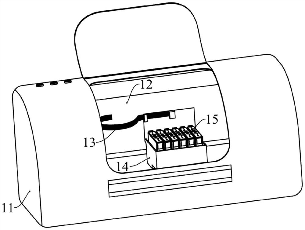
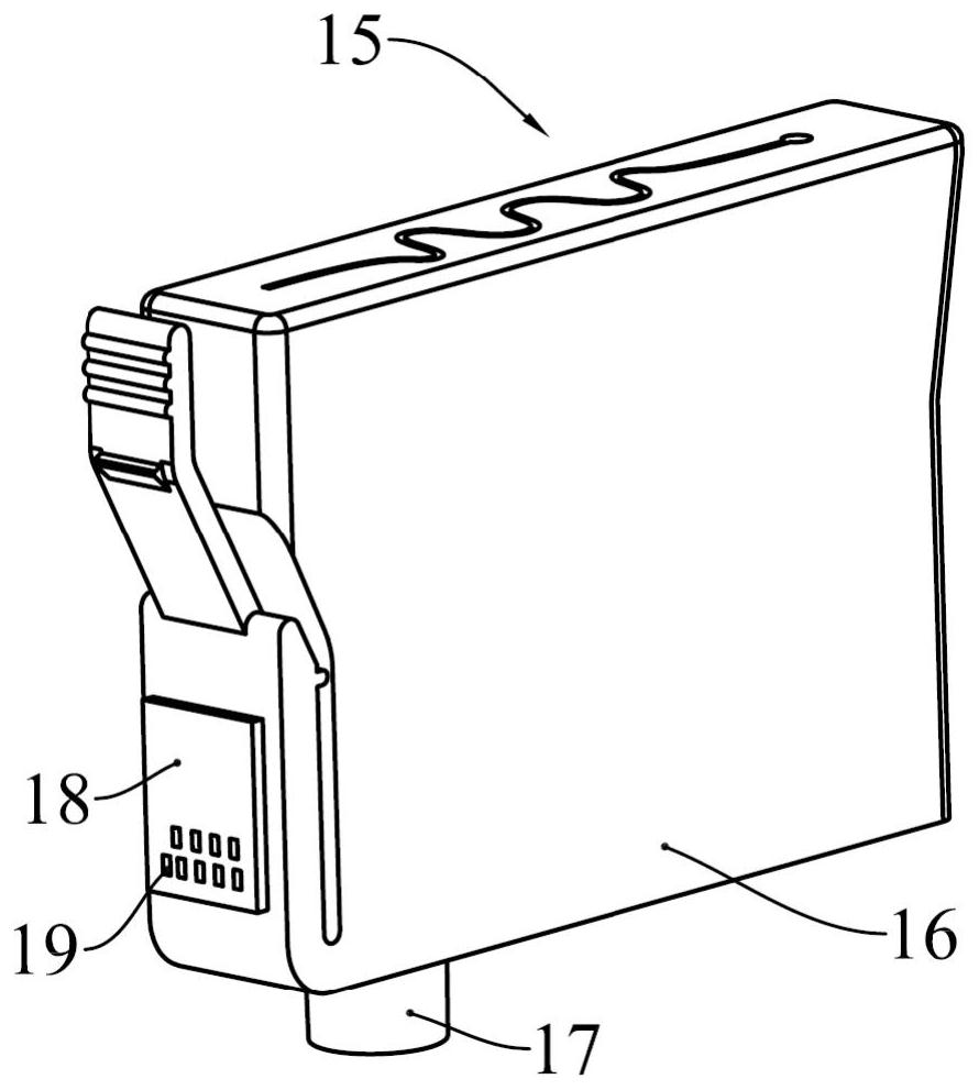
[0071] The electronic imaging device of this embodiment is an inkjet printer, which is provided with a body, and a printing carriage is formed in the body, and a connecting piece can be installed on the printing carriage, the ink cartridge is installed in the printing carriage, and the connecting piece is connected to the outer wall of the ink cartridge Between the printed word car. Moreover, the ink cartridge has a shell, which encloses a cavity for containing ink, and an ink outlet communicating with the cavity is arranged below the cavity, and the ink in the cavity can flow out through the ink outlet. Moreover, an ink cartridge chip is detachably mounted on an outer wall of the casing.

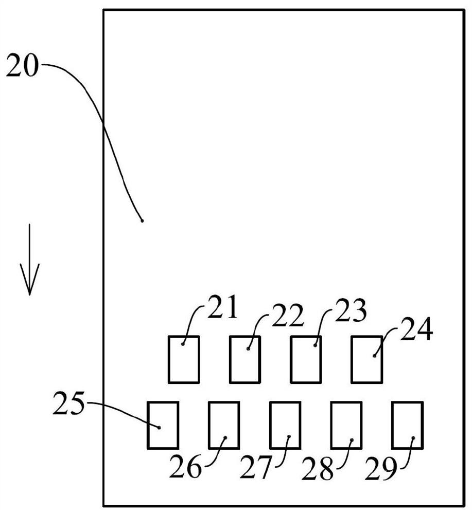
[0072] The ink cartridge chip has a substrate, and a side of the substrate close to the printing carriage is provided with multiple connection terminals. Preferably, the multiple connection terminals are arranged in two rows. A memory is provided on the other side of the substrate, and the...

no. 2 example

[0094] see Figure 15 , the connector 100 of the present embodiment has a flexible circuit board, a plurality of contact portions are arranged on the flexible circuit board, and the connector 100 corresponds to four word car units, therefore, the connector 100 is divided into four parts, which are respectively The first part 110 , the second part 120 , the third part 130 and the fourth part 140 are provided with locking slots in two adjacent parts, and each part is provided with an open slot.

[0095] A plurality of contact portions are arranged on the surface of the connector 100 close to the printing carriage, from Figure 15 It can be seen that two contact parts 111, 114 are provided on the first part 110, two contact parts 141, 144 are provided on the fourth part 110, and the four contact parts 111, 114, 141, 144 are electrically connected by metal wires. . However, no contact portion is provided on the second part 120 and the third part 130 . It can be seen that the fo...

no. 3 example

[0099] see Figure 16 , the connector 200 of the present embodiment has a flexible circuit board, a plurality of contact portions are arranged on the flexible circuit board, and the connector 200 corresponds to four word car units, therefore, the connector 200 is divided into four parts, which are respectively The first part 210 , the second part 220 , the third part 230 and the fourth part 240 are provided with locking slots in two adjacent parts, and each part is provided with an open slot.

[0100] A plurality of contact portions are arranged on the surface of the connector 200 close to the printing carriage, from Figure 16 It can be seen that compared with the first embodiment, this embodiment only sets the contact portion 211 and the contact portion 215 on the first part 210, and only sets the contact portion 244 and the contact portion 249 on the fourth part 240. The first functional stylus corresponding to the contact portion 211 inputs the detection signal and receiv...


PUM


Abstract

The invention provides a connecting piece, a consumable chip, a consumable container, an electronic imaging device and a method for installing the connecting piece and the consumable container. The connecting piece comprises at least two contact parts, the at least two contact parts are electrically connected with first function contact pins corresponding to the electronic imaging device respectively, the first function contact pins are detection contact pin, the at least two contact parts electrically connected with the first functional contact pins are electrically connected through electric conduction parts, and/or the at least two contact parts are electrically connected with second functional contact pins corresponding to the electronic imaging equipment respectively, the second functional contact pins are the contact pins which apply high-voltage signals, and the plurality of contact parts electrically connected with the second functional contact pins are electrically connected through the electric conduction parts. The consumable chip is arranged on the consumable container, and the consumable container is installed on the electronic imaging device. The invention further provides the method for installing the connecting piece and the consumable container to the electronic imaging equipment. According to the invention, the situation that a memory on the consumable chip is damaged due to the fact that the memory is loaded with the high-voltage signals can be avoided.

Description

technical field [0001] The present invention relates to the technical field of electronic imaging, in particular to a connector, a consumable chip used in conjunction with the connector, a consumable container and an electronic imaging device, and a method for installing the connector and the consumable container. Background technique [0002] As common office equipment, electronic imaging equipment provides great convenience for modern office. Common electronic imaging equipment includes printers, copiers, etc. Existing printers are divided into inkjet printers and laser printers. Inkjet printers use ink The ink cartridge used as the ink cartridge ejects ink to the paper to form the text or pattern to be printed on the paper; the laser printer uses the toner cartridge containing the toner as the ink cartridge to form the text or pattern to be printed on the medium. [0003] see figure 1 , an existing color inkjet printer has a casing 11, figure 1 The inkjet printer is sho...

Claims


Application Information

Patent Timeline
IPC IPC(8): B41J2/175G03G15/08
CPCB41J2/17546G03G15/0863
Inventor 文冠果罗寿杰车秩柳
Owner ZHUHAI TIANWEI TECH DEV CO LTD
Why Eureka
Try Eureka