Vehicle charging pile

A technology for charging piles and vehicles, applied in charging stations, electric vehicle charging technology, vehicle energy storage, etc., to achieve the effects of convenient transportation and on-site construction, reducing civil engineering requirements, and shortening the station construction period

Pending Publication Date: 2022-01-18
XJ ELECTRIC +1
View PDF0 Cites 0 Cited by
  • Summary
  • Abstract
  • Description
  • Claims
  • Application Information

AI Technical Summary

Problems solved by technology

[0003] The purpose of the present invention is to provide a vehicle charging column to solve the charging of vehicles in multi-storey buildings, meet the long-distance and large-span use requirements across both sides of the road, effectively solve the problem of large-span vertical deformation, and adopt a modular structure for docking, Technical issues such as convenient transportation and on-site construction

Method used


Image

  • Vehicle charging pile
  • Vehicle charging pile
  • Vehicle charging pile

Examples


Embodiment Construction

[0032] In order to make the object, technical solution and advantages of the present invention clearer, the present invention will be further described in detail below in combination with specific embodiments and with reference to the accompanying drawings. It should be understood that these descriptions are exemplary only, and are not intended to limit the scope of the present invention. Also, in the following description, descriptions of well-known structures and techniques are omitted to avoid unnecessarily obscuring the concept of the present invention.

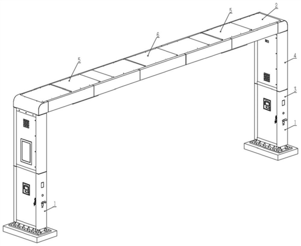
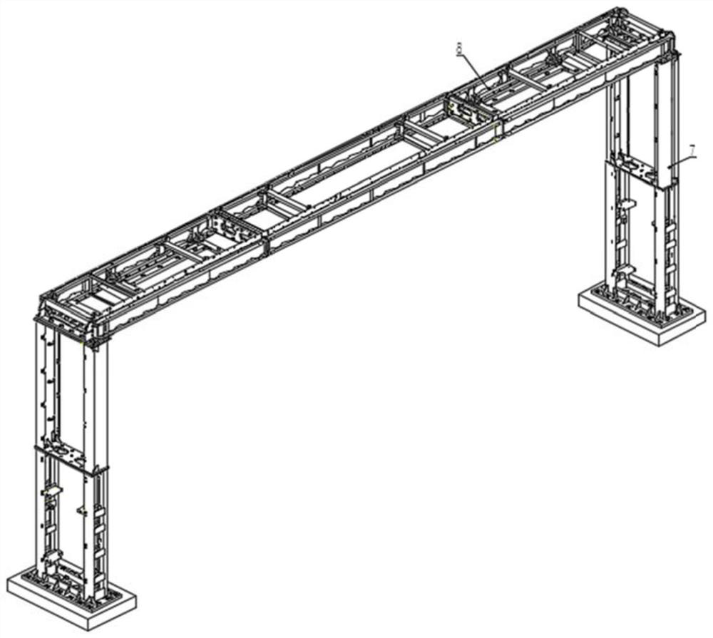
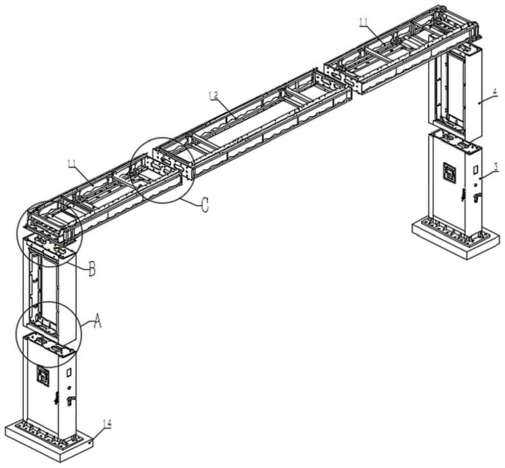
[0033] The vehicle charging column of the present invention is as follows: Figure 1 to Figure 9 shown.

[0034] like figure 1 As shown, the vehicle charging column includes a column part 1 and a top beam part 2, and the upper side of the column part 1 overlaps with the top beam part 2 to form a gantry structure.

[0035] The column part 1 includes a lower electrical module 3 , an upper wiring module 4 and a column fra...


PUM


Abstract

The invention relate to a vehicle charging pile comprising a stand column part and a top cross beam part, and the upper side of the stand column part is in lap joint with the top cross beam part to form a gantry type structure; the stand column part comprises a lower electrical module, an upper wiring module and a stand column framework. The top cross beam part comprises a charging mechanism mounting module, a middle connecting module and a top cross beam framework. The lower electrical module and the upper wiring module of the stand column part are connected through a stand column framework flange. And the charging mechanism mounting module and the middle connecting module of the top cross beam part are connected through a top cross beam framework flange. According to the vehicle charging pile, the gantry type structure is adopted, the civil engineering requirement can be lowered, and the vehicle charging pile meets the large-span installation requirements of the multi-story building ground and the two sides of a crossing road; modularized structure butt joint facilitates transportation and on-site construction, and shortens the station building period. The framework of the top cross beam is of a truss structure, and the problem of large-span vertical deformation is effectively solved.

Description

technical field [0001] The invention relates to the field of new energy technologies, in particular to a vehicle charging pile. Background technique [0002] At present, in the field of new energy technology, vehicle charging columns are generally installed on the side of the roadway on the ground. In order to meet the connection strength requirements, it is necessary to dig enough deep earthwork on the ground to form a reinforced concrete foundation. With the development of society, many parking lots are multi-storey buildings, which is obviously impossible on the upper ground of multi-storey buildings. Conventional charging columns are generally arranged on one side of the roadside, and the long-span scheme across both sides of the road is not yet mature, and generally adopts an integral welded skeleton, which is large in size, which is not conducive to transportation and on-site construction. Conventional charging columns are generally arranged on one side of the roadsid...

Claims


Application Information

Patent Timeline
IPC IPC(8): B60L53/31B60L53/30
CPCB60L53/31B60L53/30Y02T10/70Y02T10/7072Y02T90/12
Inventor 杜永平殷帅兵李明明高庆勇魏伟穆贝贝方春阳郑召敏闫建华白志红
Owner XJ ELECTRIC
Why Eureka
Try Eureka