Filling valve for filling machine

A filling valve and filling machine technology, applied in packaging, valve details, valve devices, etc., can solve the problems of freezing the filling valve, liquid is prone to freezing, and the valve body does not have anti-freezing function, so as to prevent Frozen effect

Pending Publication Date: 2022-01-18
新沂百博瑞机械有限公司
View PDF1 Cites 1 Cited by
  • Summary
  • Abstract
  • Description
  • Claims
  • Application Information

AI Technical Summary

Problems solved by technology

[0004] However, the technical solution provided by this patent does not have the antifreeze function for the valve body. When the filling valve is filled with liquid in the winter environment in northern China and stands still, due to the

Method used


Image

  • Filling valve for filling machine
  • Filling valve for filling machine
  • Filling valve for filling machine

Examples


Example Embodiment

[0045] Example 1

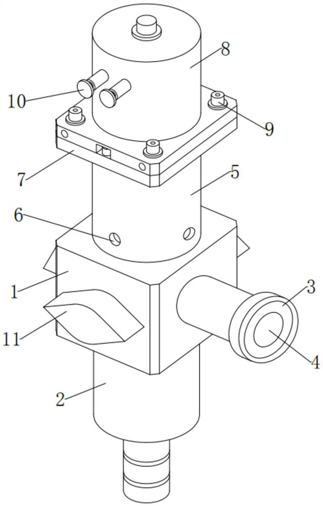
[0046] see Figure 1-2 , in an embodiment of the present invention, a filling valve for a filling machine, comprising:

[0047] Valve body 1, the central position of the bottom end of the valve body 1 is fixedly installed with the filling nozzle 2, the central position of the outer surface on the right side of the valve body 1 is fixedly installed with the input connecting pipe 3, and the central position of the right side of the input connecting pipe 3 is provided with a valve Inlet 4, the top central position of the valve body 1 is fixedly installed with a connecting seat 5, the four corners of the lower end of the connecting seat 5 are movable and installed with set screws 6, and the top position of the connecting seat 5 is fixedly installed with an end plate 7, an end plate 7 A cylinder 8 is fixedly installed at the central position of the top end, bolt assemblies 9 are movably installed at the top four corners of the end plate 7, and two interface piec...

Example Embodiment

[0057] Example 2

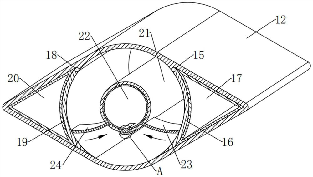
[0058] see figure 2 , Figure 4-5 Compared with Embodiment 1, the embodiment of the present invention differs in that: the preprocessing component 13 includes:

[0059] Right shaft 15, the upper end of the right inner wall of the housing 12 is rotated in the front and rear horizontal direction, and the right shaft 15 is installed, and the front and rear ends of the right shaft 15 are rotatably installed at the upper right end of the front and rear inner walls of the housing 12;

[0060] Right rotating plate 16, the outer surface of the bottom side of right rotating shaft 15 is surrounded and fixedly installed with right rotating plate 16. It has a magnetic property different from that of the housing 12, and the bottom outer surface of the right rotating plate 16 is magnetically attracted to the lower surface of the right inner wall of the housing 12 under normal conditions;

[0061] Here, the right turning plate 16 has an outward appearance on a longitud...

Example Embodiment

[0073] Example 3

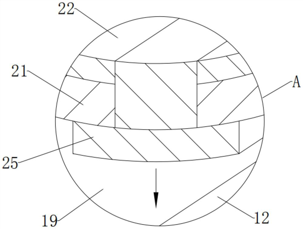
[0074] see Figure 2-4 and Image 6 Compared with Embodiment 1, the embodiment of the present invention differs in that: the heating assembly 14 includes:

[0075] Inner shell 21, the inner shell 21 is fixedly installed in the central position of the shell 12, the appearance of the inner shell 21 is a hollow circular shape on a longitudinal section, and the outer surfaces of the front and rear sides of the inner shell 21 are fixedly mounted on the shell 12 The inner diameter of the inner shell 21 is 2 / 3 of the inner diameter of the housing 12, and the right lower end and the lower left end of the inner shell 21 are obliquely penetrated with a right chute and a left chute, and the bottom end of the inner shell 21 There is a through groove through the upper and lower ends at the middle end of the front part;

[0076] Here, the inner casing 21 and its appearance are set as a hollow circular shape on a longitudinal section, and its inner diameter is 2 / 3 of th...


PUM


Abstract

The invention provides a filling valve for a filling machine. The filling valve comprises anti-freezing components which are fixedly arranged at the central positions of the outer surfaces of the front side, the rear side and the left side of a valve body and can prevent the valve body from being frozen, wherein each anti-freezing component comprise a shell, pretreatment components capable of making preparation in advance before residual liquid in the valve body is frozen, and heating components capable of rising the temperature outside the valve body; the shells are fixedly installed in the centers of the outer surfaces of the front side, the rear side and the left side of the valve body; the pretreatment components are movably installed at the left end and the right end in each shell correspondingly; and the heating components are movably installed between the center in each shell and the left and right lower ends. According to the filling valve for the filling machine, the anti-freezing function can be achieved outside the valve body, when the filling valve is subjected to liquid filling in the winter environment of northern China and stands still, even if the temperature outside the valve is low, residual liquid in the valve is not prone to freezing, the possible freezing fault can be eliminated in time, the filling valve is prevented from being damaged by freezing, and the subsequent use effect is ensured.

Description

technical field [0001] The invention relates to the field of filling machinery and equipment, and more specifically relates to a filling valve for a filling machine. Background technique [0002] The traditional filling valve is filled through the standard pneumatic angle seat valve control switch, which only has two actions of opening and closing, and does not play a buffer role in the stamping of the material during filling, which will cause anti-foaming of the material, Inaccurate filling volume and other problems, as well as the length of the filling mouth can not be effectively controlled, resulting in dripping after the valve is closed, polluting the bottle mouth; in addition, due to the frequent movement of the filling valve, the pneumatic angle seat valve After the unit seal is worn out, material leakage and channeling will occur, which will have a great impact on the hygienic requirements and filling accuracy of filling. [0003] In view of the above problems, rega...

Claims


Application Information

Patent Timeline
IPC IPC(8): B67C3/26B67C3/22F16K49/00
CPCB67C3/2617B67C3/22F16K49/00B67C2003/2671
Inventor 胡功名
Owner 新沂百博瑞机械有限公司
Why Eureka
Try Eureka