
Novel high-pressure plunger pump fluid end structure

A high-pressure plunger pump and hydraulic end technology, which is applied in the field of the hydraulic end structure of the new high-pressure plunger pump, can solve the problem that the discharge check valve cannot be closed in time, the service life of the high-pressure reciprocating pump is affected, and the response of the discharge valve plate is inconsistent. Timely and other issues, to achieve the effect of sufficient opening and closing characteristics, saving materials, and reducing size

Pending Publication Date: 2022-01-18
TIANJIN TONGJIE HIGH PRESSURE PUMP
View PDF1 Cites 0 Cited by
  • Summary
  • Abstract
  • Description
  • Claims
  • Application Information

AI Technical Summary

Problems solved by technology

[0005] Due to the inconsistency between the ideal liquid inlet working condition and the liquid discharging working condition, there is insufficient liquid inlet in the actual work, which will cause the vibration of the pump body, unstable operation, and high operating noise. If things go on like this, it will affect the service life of the high-pressure reciprocating pump; The valve plate does not respond in time, and the discharge check valve cannot be closed in time, resulting in low volumetric efficiency of the valve group

Method used


Image

  • Novel high-pressure plunger pump fluid end structure
  • Novel high-pressure plunger pump fluid end structure
  • Novel high-pressure plunger pump fluid end structure

Examples


Embodiment 1

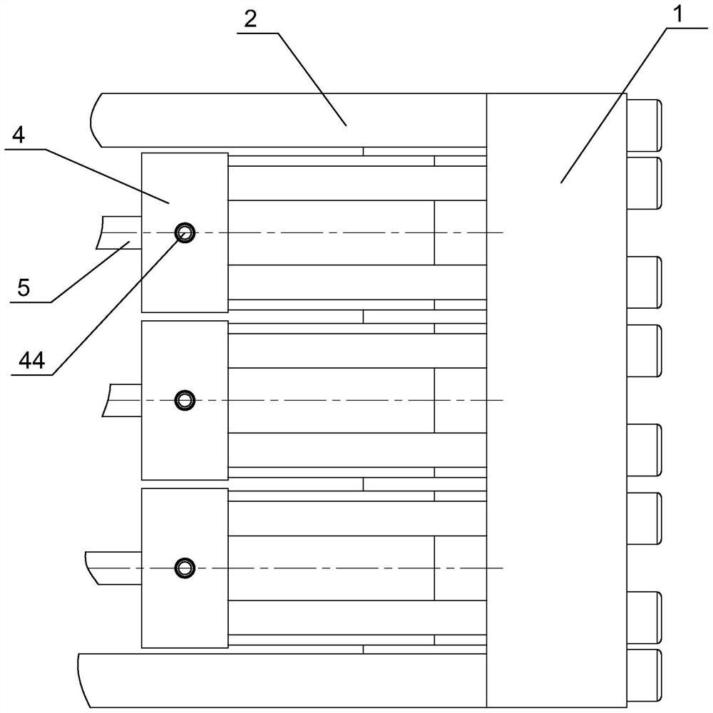
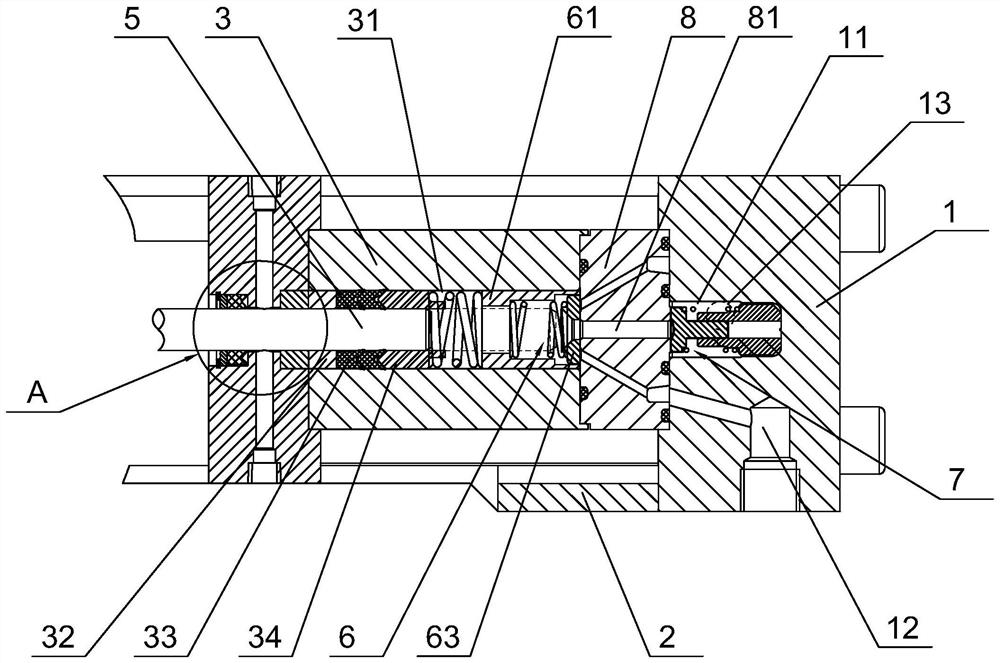
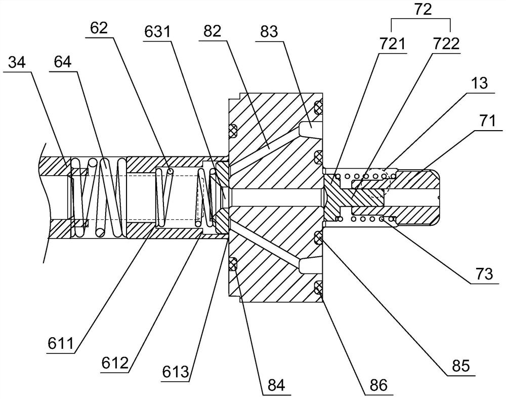
[0058] refer to figure 1 and figure 2 , including a bracket 2, a pump head 1, a plunger 5 and a low-pressure water seal 4, the pump head 1 and the low-pressure water seal 4 are respectively fixed at both ends of the bracket 2. The bracket 2 is an integral bracket, and the bracket 2 is provided with three sets of stuffing boxes 3 and three sets of valve group assemblies. The valve group assembly includes a liquid inlet check valve 6, a liquid discharge check valve 7, and a liquid inlet and discharge valve body 8. The pump head 1 is provided with a liquid discharge chamber 11, and the liquid discharge check valve 7 is located in the liquid discharge chamber 11. Inside, the stuffing box 3 is provided with a liquid inlet chamber 31, and the liquid inlet check valve 6 is arranged in the liquid inlet chamber 31, and the liquid inlet check valve 6 and the liquid discharge check valve 7 are located on the same axis. The liquid inlet and discharge valve body is arranged between the ...


PUM


Abstract

The invention discloses a novel high-pressure plunger pump fluid end structure. The structure comprises a bracket, a pump head, a plunger and a low-pressure water seal, three groups of stuffing boxes and three groups of valve group assemblies are arranged in the bracket, each valve group assembly comprises a liquid inlet one-way valve, a liquid discharge one-way valve and a liquid inlet and discharge valve body, the liquid inlet and discharge valve bodies are arranged between the stuffing boxes and the pump head, two ends of the liquid inlet and discharge valve bodies abut against the liquid inlet one-way valves and the liquid discharge one-way valves respectively. The plunger penetrates through the low-pressure water seal and is in sliding connection with the stuffing boxes, and the liquid inlet one-way valves and the liquid discharge one-way valves can be opened or closed through reciprocating motion of the plunger. The liquid discharging one-way valve comprises a liquid discharging limiting sleeve, a liquid discharging valve element and a liquid discharging spring. The liquid inlet one-way valve comprises a liquid inlet limiting sleeve, a first liquid inlet spring, a liquid inlet valve plate and a second liquid inlet spring. Compared with the prior art, the structure has the characteristics of sufficient liquid inlet and timely opening and closing, vibration can be reduced, noise can be lowered, the service life can be prolonged, and the volume efficiency of a valve bank can be improved.

Description

technical field [0001] The invention relates to the technical field of high-pressure reciprocating pumps, in particular to a novel hydraulic end structure of a high-pressure plunger pump. Background technique [0002] High-pressure reciprocating pumps are widely used in various industries, such as process pumps in petroleum, chemical and fertilizer industries, water injection pumps in oil fields and salt mines, pressure test pumps and booster pumps in steel pipes and pressure vessels, construction, shipbuilding, chemical and other industries. High-pressure cleaning and descaling, boiler feed water, transmission source of hydraulic machinery. [0003] Among them, the high-pressure reciprocating plunger pump, also known as the plunger pump, is an important device of the hydraulic system. It relies on the reciprocating movement of the plunger in the cylinder to change the volume of the sealed working chamber to realize the suction and compression of the medium. It has the adva...

Claims


Application Information

Patent Timeline
Patent Type & Authority Applications(China)
IPC IPC(8): F04B53/10F04B53/08F04B53/00F04B53/02
CPCF04B53/109F04B53/10F04B53/08F04B53/00F04B53/02
Inventor 齐彬田双志王征
Owner TIANJIN TONGJIE HIGH PRESSURE PUMP
Learn More