Installation method for improving contact rigidity between piezoelectric element and conducting strips

A piezoelectric element and contact stiffness technology, which is applied in the installation field of improving the contact stiffness between the piezoelectric element and the conductive sheet, can solve the problems of crushing the piezoelectric element, etc. Effect

Pending Publication Date: 2022-01-18
CHENGDU KAITIAN ELECTRONICS
View PDF4 Cites 0 Cited by
  • Summary
  • Abstract
  • Description
  • Claims
  • Application Information

AI Technical Summary

Problems solved by technology

This method can improve the contact stiffness of the piezoelectric element to a certain extent, but it also encounters certain difficulties in implementation because the pretightening force is too large to crush the piezoelectric element, resulting in unloading of the pretightening force

Method used


Image

  • Installation method for improving contact rigidity between piezoelectric element and conducting strips
  • Installation method for improving contact rigidity between piezoelectric element and conducting strips
  • Installation method for improving contact rigidity between piezoelectric element and conducting strips

Examples


Embodiment 1

[0035] This embodiment provides an installation method for improving the contact stiffness between the piezoelectric element and the conductive sheet, including the following steps:

[0036] (1) A conductive sheet is respectively installed on the two electrode surfaces of the piezoelectric element;

[0037] (2) A metal foil is arranged between the piezoelectric element and the conductive sheet;

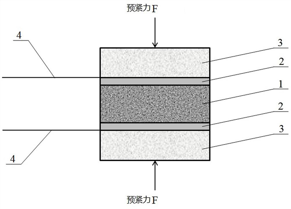
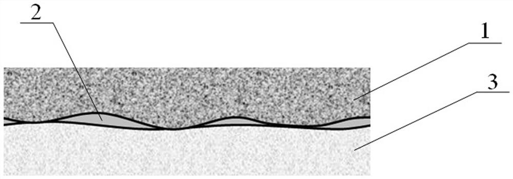
[0038] (3) Apply a uniform pre-tightening force to the conductive sheets on both sides, so that the metal foil between the piezoelectric element and the conductive sheet is stretched and deformed, and the microscopic contact gap between the piezoelectric element and the conductive sheet is filled.

[0039] The specific installation structure after installation, such as figure 1 As shown, the conductive sheet 3, the metal foil 2, the piezoelectric element 1, the metal foil 2, and the conductive sheet 3 are sequentially stacked and installed. By applying the pre-tightening force F to ...

Embodiment 2

[0041] In this embodiment, on the basis of the above embodiments, the material of the conductive sheet is further limited, and the conductive sheet is made of conductive glass material. The conductive sheet made of conductive glass material has high hardness and very small roughness on the surface, thereby further improving the contact rigidity between the piezoelectric element and the conductive sheet. Other parts of this embodiment are the same as those of the foregoing embodiment, and will not be repeated here.

Embodiment 3

[0043] In this embodiment, on the basis of the above embodiments, the material of the conductive glass is further limited, and the material of the conductive glass is ITO conductive film glass. In order to ensure high rigidity and small roughness of the surface of the conductive sheet, the preferred conductive glass material here is ITO conductive film glass, and other conductive glass materials that can ensure high steel height and small roughness of the conductive sheet surface can also be selected. Other parts of this embodiment are the same as those of the foregoing embodiment, and will not be repeated here.


PUM

PropertyMeasurementUnit
thicknessaaaaaaaaaa
thicknessaaaaaaaaaa
thicknessaaaaaaaaaa

Abstract

The invention discloses an installation method for improving the contact rigidity between a piezoelectric element and conducting strips. The installation method comprises the following steps that (1) the conducting strips are installed on the surfaces of two electrodes of the piezoelectric element respectively; 2) a metal foil is arranged between the piezoelectric element and the conducting strips; and (3) uniform pre-tightening force is applied to the conducting strips on the two sides so that the metal foil between the piezoelectric element and the conducting strips extends and deforms, and the microscopic contact gaps between the piezoelectric element and the conducting strips are filled. According to the invention, the metal foil is arranged between the piezoelectric element and the conducting strips so that the metal foil fills the microscopic contact gaps between the piezoelectric element and the conducting strips to improve the contact rigidity between the piezoelectric element and the conducting strips; by using the conducting strips with the glass as the base material, the surface of the conducting strips has high hardness and tiny roughness so as to improve the contact rigidity between the piezoelectric element and the conducting strips, and the manufacturing process is simple, the manufacturing cost is low and wide popularization and application are facilitated.

Description

technical field [0001] The invention relates to the technical field of vibration measurement, in particular to an installation method for increasing the contact stiffness between a piezoelectric element and a conductive sheet. Background technique [0002] As a mechanical measurement device, piezoelectric vibration sensors play an important role in the health diagnosis of key mechanical equipment in the fields of aerospace, aviation and nuclear industries. Relevant studies have shown that the early failure symptoms of mechanical equipment are mainly high-frequency vibrations, and the lower-frequency vibrations will gradually appear as the failures intensify. Therefore, if you want to monitor early signs of mechanical equipment failure, you need a vibration sensor with high-frequency measurement capabilities. [0003] After the piezoelectric element is installed and fixed inside the sensor, the contact stiffness of the fixed surface directly affects the installation natural ...

Claims


Application Information

Patent Timeline
Patent Type & Authority Applications(China)
IPC IPC(8): G01H11/08
CPCG01H11/08
Inventor 金城王启迪熊艳梅王瑞琪黄伟
Owner CHENGDU KAITIAN ELECTRONICS
Why Eureka
Try Eureka