Vacuum transmitter monitoring and management method

A technology for monitoring and management of transmitters, applied in the field of transmitters, can solve problems such as waste of resources, and achieve the effect of improving use efficiency and achieving reliability prediction.

Pending Publication Date: 2022-01-18
THE 724TH RES INST OF CHINA SHIPBUILDING IND
View PDF0 Cites 0 Cited by
  • Summary
  • Abstract
  • Description
  • Claims
  • Application Information

AI Technical Summary

Problems solved by technology

When the transmitter needs to work for a long time to complete the task, in order to improve the certainty of the stable operation of the radar system and ensure the completion of the task, the user often replaces the one with normal indicators only because the cumulative working time is close to the guaranteed use time. Vacuum tubes, resulting in a serious waste of resources

Method used


Image

  • Vacuum transmitter monitoring and management method
  • Vacuum transmitter monitoring and management method

Examples


Embodiment Construction

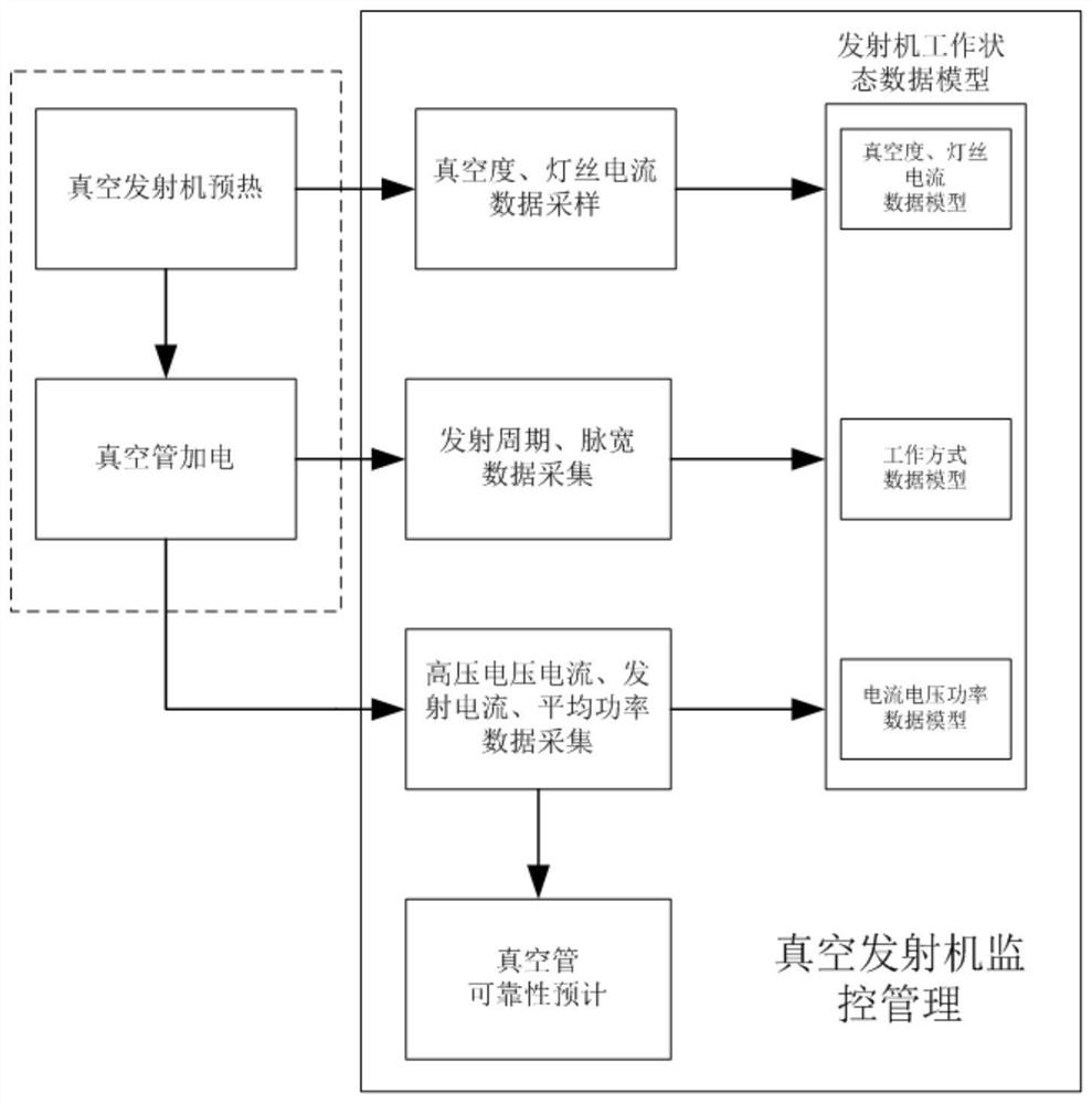
[0021] In order to verify the feasibility of the vacuum tube transmitter monitoring and management method, a radar vacuum tube transmitter is taken as an example to build a transmitter working data model.

[0022] Step 1. Construct the data model of the normal working state of the vacuum tube transmitter. The vacuum tube of the transmitter requires a titanium pump voltage of 3kV, a titanium pump current of 0, and a filament current of 2.80A (determined by the vacuum tube itself). The typical working mode of the transmitter: the period is XμS, the pulse width is YμS, and the duty cycle is Y / X=δ. The transmitter voltage and current parameters corresponding to this working mode are as follows: high voltage power supply voltage 27.5kV, high voltage power supply current (I 总 )200mA, collector current (I 收 )180mA, tube body current (I 管 ) 20mA, average output power 900W.

[0023] So the transmitter working data model:

[0024] Vacuum degree of vacuum tube: Titanium pump voltage...


PUM


Abstract

The invention provides a vacuum transmitter monitoring and management method, which comprises the following steps of: constructing a data model of a vacuum tube transmitter in a normal working state, acquiring titanium pump power supply voltage and current and filament current in a preheating state, comparing sampled data with data in a data model, and determining that a vacuum tube can be powered up; under the working state of the vacuum tube, collecting working parameters of the transmitter during working; determining the working mode of the current transmitter according to the collected period and the pulse width parameter; converting the current of a collector and the current of a high-voltage power supply into a vacuum tube emission passing rate, and calculating the vacuum tube emission passing rate; comparing the sampling data with the data in the data model, and sending an alarm signal when the sampling data exceeds the range of the normal data; and predicting the reliability of the vacuum tube. According to the invention, remote real-time monitoring management of the vacuum transmitter and reliability prediction of the vacuum tube can be realized by remote monitoring of the working state of the vacuum transmitter and reliability prediction of the vacuum tube.

Description

technical field [0001] The present invention belongs to transmitter technology. Background technique [0002] In a radar system, the transmitter is responsible for amplifying the low-power radio frequency signal generated by the frequency source or directly self-oscillating to generate a high-power transmission signal. The basic principle of the transmitter is to convert electrical energy into electromagnetic energy. [0003] In order for the vacuum transmitter to start up normally, it is first necessary to confirm the vacuum degree of the vacuum tube, and secondly, to preheat the filament of the vacuum tube. After the preheating is completed, the vacuum tube can be powered on. Among transmitters that generate high-power transmission signals, most use high-voltage power supplies as power supplies. When the transmitter works with high voltage, the vacuum tube is controlled by the modulator to work alternately on and off. When the high-voltage power supply and modulator are...

Claims


Application Information

Patent Timeline
IPC IPC(8): G01S7/282G01S7/35G01S7/36
CPCG01S7/282G01S7/35G01S7/36
Inventor 张言徐伟张帅
Owner THE 724TH RES INST OF CHINA SHIPBUILDING IND
Why Eureka
Try Eureka