Combined conductive device of motor shaft current protection structure

A technology of current protection and conductive devices, which is applied in the direction of electromechanical devices, structural connections, electric components, etc., can solve the problems of increasing the internal installation space and cost of the motor, and the inconvenience of rectification of existing motors, etc., to achieve the effect of platformization and serialization

Pending Publication Date: 2022-01-18
ZHEJIANG ZHONGCHE SHANGCHI ELECTRIC CO LTD
View PDF0 Cites 1 Cited by
  • Summary
  • Abstract
  • Description
  • Claims
  • Application Information

AI Technical Summary

Problems solved by technology

[0003] In the field of new energy vehicle motor applications, due to factors such as product structure and cost, insulating end caps and insulating bearings are rarely used. The use of grounding carbon brushes or conductive rings requires additional consideration of the installation space of the motor, and it is very difficult for the motor that has already been installed. Difficult to rectify
[0004] At present, in the field of new energy vehicle motors, the shaft current problem is mostly treated with a conductive ring. The conductive ring conducts electricity through the conductive fiber fixed in the ring and the shaft. Compared with the ground carbon brush, the conductive fiber has good conductivity and wear resistance. , maintenance-free and other advantages, due to the large conductive ring, it will need to increase the installation space and cost inside the motor, and it is very inconvenient for the rectification of the existing motor

Method used


Image

  • Combined conductive device of motor shaft current protection structure
  • Combined conductive device of motor shaft current protection structure
  • Combined conductive device of motor shaft current protection structure

Examples


Embodiment Construction

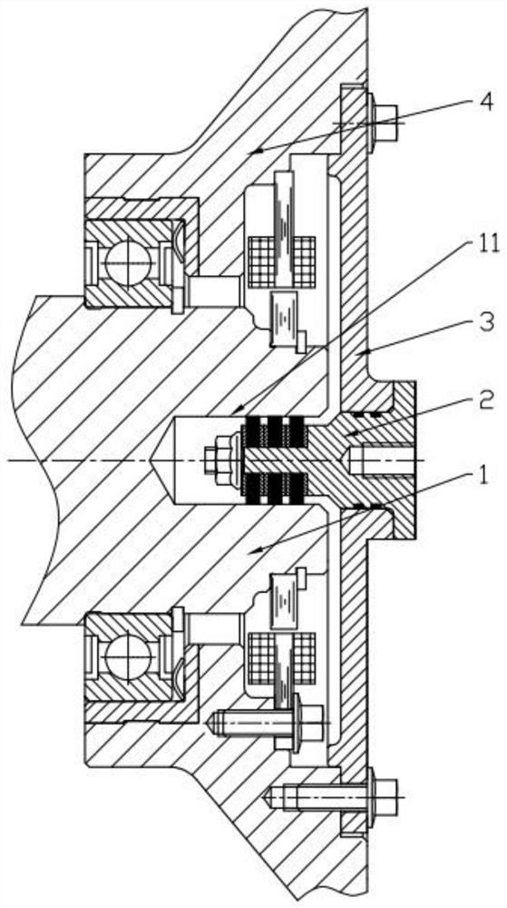
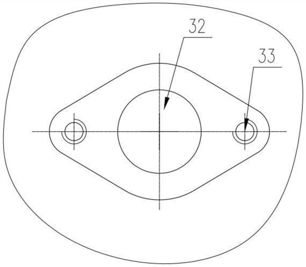
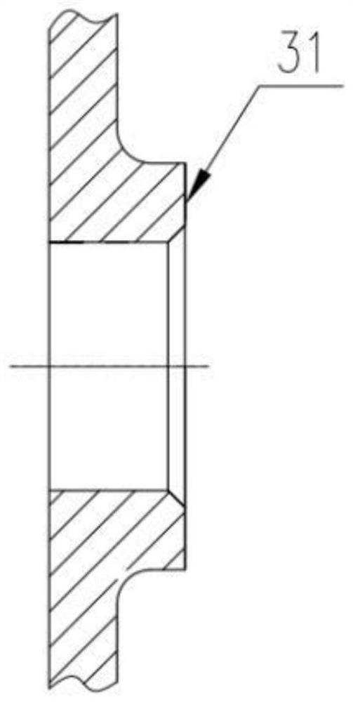
[0039] refer to Figure 1 to Figure 20 Embodiments of the present invention will be further described.

[0040] In the description of the present invention, it should be noted that for orientation words, such as the term "center", "horizontal (X)", "longitudinal (Y)", "vertical (Z)", "length", " Width", "Thickness", "Top", "Bottom", "Front", "Back", "Left", "Right", "Vertical", "Horizontal", "Top", "Bottom", "Inner ", "outside", "clockwise", "counterclockwise" and other indication orientations and positional relationships are based on the orientation or positional relationship shown in the drawings, and are only for the convenience of describing the present invention and simplifying the description, rather than indicating or implying the Means that a device or element must have a specific orientation, be constructed and operated in a specific orientation should not be construed as limiting the specific protection scope of the present invention.

[0041] In addition, terms su...


PUM


Abstract

The invention discloses a combined conductive device of a motor shaft current protection structure. The device comprises an electric conductor and a plurality of conductive brushes, wherein the electric conductor comprises a head part and a tail part, wherein the head part extends into an inner hole, the tail part is positioned on the outer side, the conductive brushes are fixed with the head part, the head part is rod-shaped, the plurality of conductive brushes are sequentially sleeved on the head part, and the end portion of the head part is provided with a locking structure. According to the invention,the electric conductor and the conductive brushes can be independently produced and then assembled, and the number of the conductive fibers or the number of the conductive brushes are adjusted according to the motor power, so that the conductive contact area is adjusted, and platformization and serialization are facilitated.

Description

technical field [0001] The invention belongs to the technical field of motors, and more specifically relates to a combined conductive device of a motor shaft current protection structure. Background technique [0002] Electric corrosion caused by shaft current is a common bearing failure of variable frequency motors. Due to factors such as variable frequency power supply and motor manufacturing, common mode currents and differential mode currents will be formed on the bearings when the motor is running. The method of reducing and suppressing the shaft current, in addition to adding filtering on the variable frequency power supply side to reduce the common mode voltage, the solution on the motor side is mainly from the two aspects of "blocking" and "draining". The "blocking" methods are: Insulated end caps, insulating bearings, etc. are used. The "sparse" method is to short-circuit the housing and the rotating shaft by adding grounding carbon brushes, conductive rings, auxili...

Claims


Application Information

Patent Timeline
Patent Type & Authority Applications(China)
IPC IPC(8): H02K11/00H02K11/20H02K5/16
CPCH02K11/0094H02K11/20H02K5/16H02K5/163
Inventor 尤磊董小艳于冰王光晨张帅王丁
Owner ZHEJIANG ZHONGCHE SHANGCHI ELECTRIC CO LTD
Why Eureka
Try Eureka