
Arc-shaped sheet metal workpiece stamping mold

A stamping die and sheet metal technology, applied in the field of die, can solve the problems of easy jamming of the sleeve on the die, reduced processing efficiency, low processing efficiency, etc., achieve orderly and efficient stamping and demolding, save resource consumption, improve The effect of work efficiency

Pending Publication Date: 2022-01-21
周于昊
View PDF0 Cites 0 Cited by
  • Summary
  • Abstract
  • Description
  • Claims
  • Application Information

AI Technical Summary

Problems solved by technology

[0003] However, the existing stamping dies for arc-shaped sheet metal workpieces still have certain defects when processing sleeves, especially for stamping dies for arc-shaped sheet metal workpieces in some special environments, such as: it is inconvenient for technicians to manually remove the mold Under such circumstances, the existing stamping dies used in such environments often have the disadvantage of low processing efficiency. On the one hand, the process of feeding, cutting, and demoulding is carried out separately, which reduces the processing efficiency. On the other hand, due to After the workpiece is processed into a sleeve, the sleeve is placed on the mold, which is very inconvenient to demould, and the sleeve is easy to get stuck on the mold. Therefore, we propose a stamping die for arc-shaped sheet metal workpieces to solve the above problems

Method used


Image

  • Arc-shaped sheet metal workpiece stamping mold
  • Arc-shaped sheet metal workpiece stamping mold
  • Arc-shaped sheet metal workpiece stamping mold

Examples


Embodiment Construction

[0024] In order to make the technical means, creative features, goals and effects achieved by the present invention easy to understand, the present invention will be further described below in conjunction with specific embodiments.

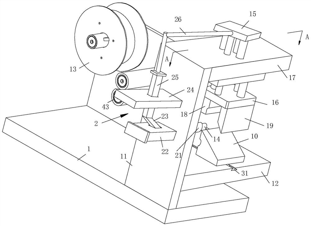
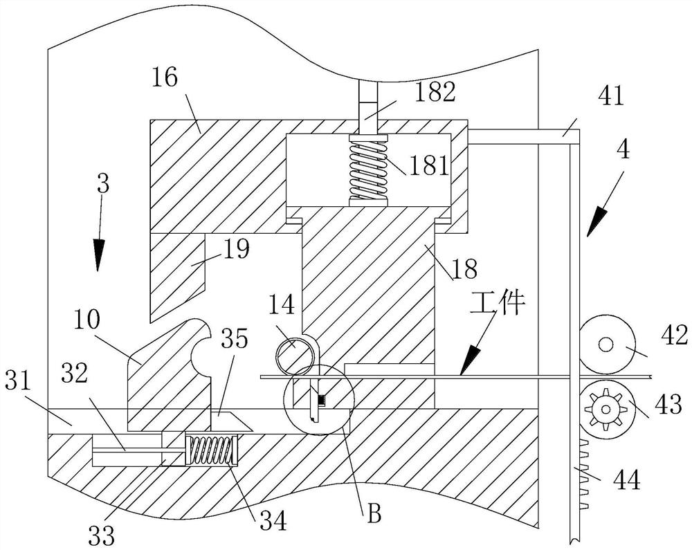
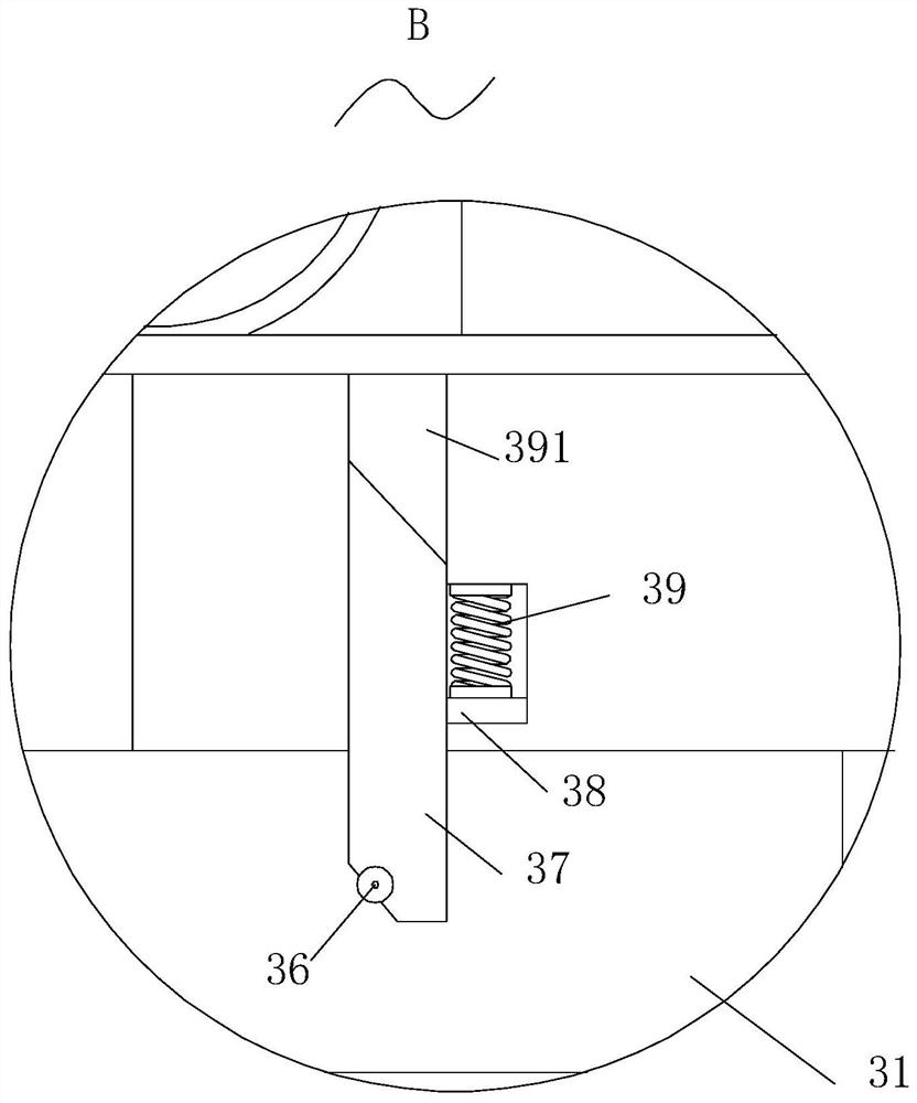
[0025] like Figure 1-Figure 6As shown, a stamping die for an arc-shaped sheet metal workpiece according to the present invention includes a base plate 1, a side plate 11 is fixedly connected to one end side of the base plate 1, and a side plate 11 is fixedly connected to the center of one side of the side plate 11. The horizontal plate 12, the horizontal plate 12 and the bottom plate 1 are located on the same side of the side plate 11, the top of the horizontal plate 12 is slidably connected with a sliding seat 10, and the connection between the sliding seat 10 and the horizontal plate 12 is provided with a cutting assembly 3. The top side of the side plate 11 is fixedly connected with a top plate 17, the top plate 17 and the horizontal plate 12 ...


PUM


Abstract

The invention relates to the field of molds, in particular to an arc-shaped sheet metal workpiece stamping mold which comprises a bottom plate, wherein a side plate is fixedly connected to the side edge of one end of the bottom plate, a transverse plate is fixedly connected to the center of one side of the side plate, the transverse plate and the bottom plate are located on the same side of the side plate, a sliding seat is slidably connected to the top of the transverse plate, a cutting assembly is arranged at the joint of the sliding seat and the transverse plate, and a top plate is fixedly connected to one side of the top of the side plate. The stamping mold is used for overcoming the defect exists under the special condition that an existing stamping mold for the arc-shaped metal plate workpiece is inconvenient for technicians to demold manually, the existing stamping mold used in the environment has the defect of low machining efficiency, on one hand, due to the fact that the procedures of feeding, cutting and demolding are carried out separately, the machining efficiency is reduced, and on the other hand, the workpiece is processed into the sleeve and then sleeved on the mold, so that the demolding is very inconvenient, and the sleeve is easily clamped on the mold.

Description

technical field [0001] The invention relates to the field of molds, in particular to a stamping mold for arc-shaped sheet metal workpieces. Background technique [0002] Stamping die is a special process equipment for processing materials (metal or non-metal) into parts (or semi-finished products) in cold stamping processing, called cold stamping die (commonly known as cold stamping die). It is widely used in the processing industry, including arc-shaped sheet metal workpieces, and the processing of sleeves is also processed by stamping. [0003] However, the existing stamping dies for arc-shaped sheet metal workpieces still have certain defects when processing sleeves, especially for stamping dies for arc-shaped sheet metal workpieces in some special environments, such as: it is inconvenient for technicians to manually remove the mold Under such circumstances, the existing stamping dies used in such environments often have the disadvantage of low processing efficiency. On ...

Claims


Application Information

Patent Timeline
IPC IPC(8): B21D37/10B21D37/12B21D43/09B21D43/28B21D45/06B21D5/12B21D55/00F16F15/067
CPCB21D37/10B21D37/12B21D43/09B21D43/287B21D45/06B21D5/12B21D55/00F16F15/067
Inventor 周于昊孔伟伟
Owner 周于昊
Learn More