An environment-friendly two-for-one twisted yarn to produce s-shaped conductor structure

An environmentally friendly, twisting technology, used in textiles and papermaking, continuous winding spinning machines, spinning machines, etc., can solve the problems of position deviation, affecting normal operation, yarn instability, etc., to improve the tightness The effect of high degree, avoid flying around, and simple structure

Active Publication Date: 2022-06-28
JIANGSU DESHUN TEXTILES
View PDF6 Cites 0 Cited by
  • Summary
  • Abstract
  • Description
  • Claims
  • Application Information

AI Technical Summary

Problems solved by technology

[0003] When the current two-for-one twisting machine adjusts the tightness of the yarn through the wire structure, it is often necessary to manually move the wire wheel rotating shaft for adjusting the tightness to a suitable position and then fix it. In the process of fixing the rotating shaft, the rotating shaft and The position of the corresponding guide pulley is likely to shift, resulting in a slight slack in the original tightness of the yarn, which will cause the yarn to be very unstable during the twisting process, thus affecting the processing effect of the entire two-for-one twister; And the current S-shaped wire structure on the two-for-one twisting machine is in the process of guiding the yarn, because the yarn will be reciprocated left and right by the winder, resulting in continuous friction between the yarn and the inner sides of the guide disc, which It will cause some cotton fluff existing on the outside of the yarn to break due to friction and fly around, which will greatly affect the air environment around the two-for-one twister, and will also cover other transmission structures of the two-for-one twister, which will affect the two-for-one twister in the long run The normal operation of the machine; at the same time, the S-type wire structure on the current two-for-one twisting machine is in the process of winding the textile thread into a yarn, the textile thread is constantly rubbing against the inside of the guide hole, which will also cause the cotton fluff on the surface of the textile thread to fly around. It will not only affect the quality of the yarn produced, but also affect the normal operation of the two-for-one twister in the long run

Method used


Image

  • An environment-friendly two-for-one twisted yarn to produce s-shaped conductor structure
  • An environment-friendly two-for-one twisted yarn to produce s-shaped conductor structure
  • An environment-friendly two-for-one twisted yarn to produce s-shaped conductor structure

Examples


Embodiment 1

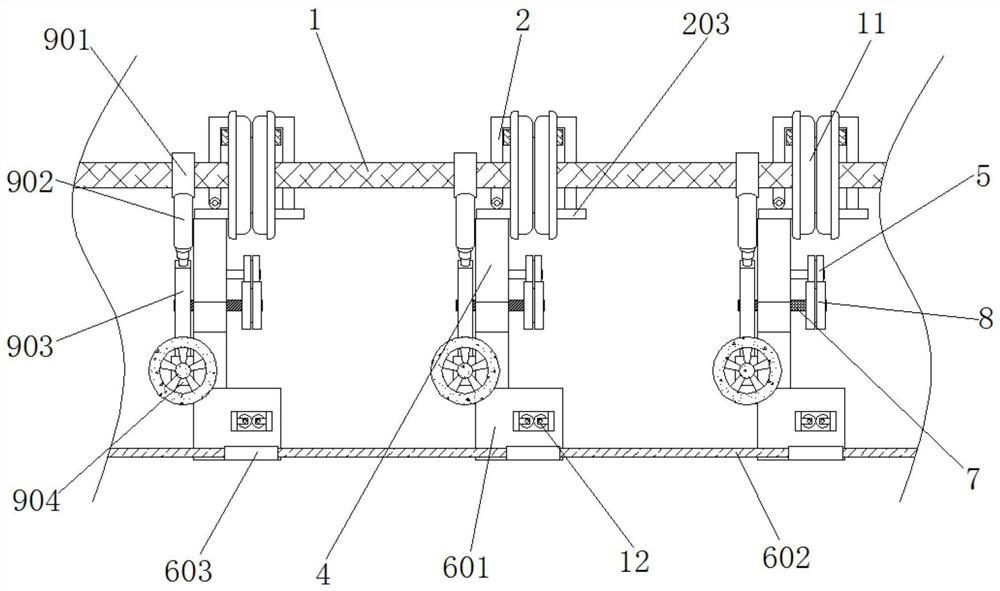
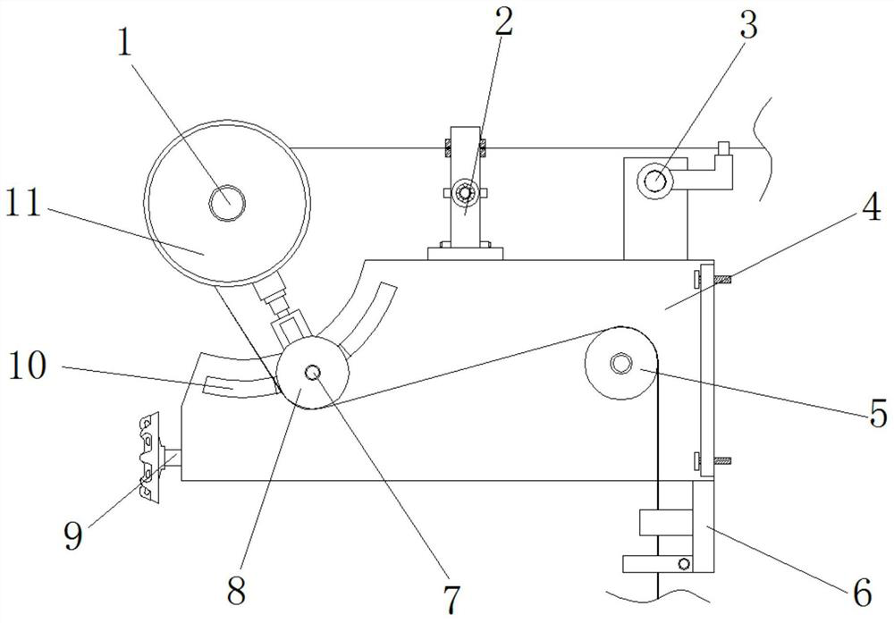
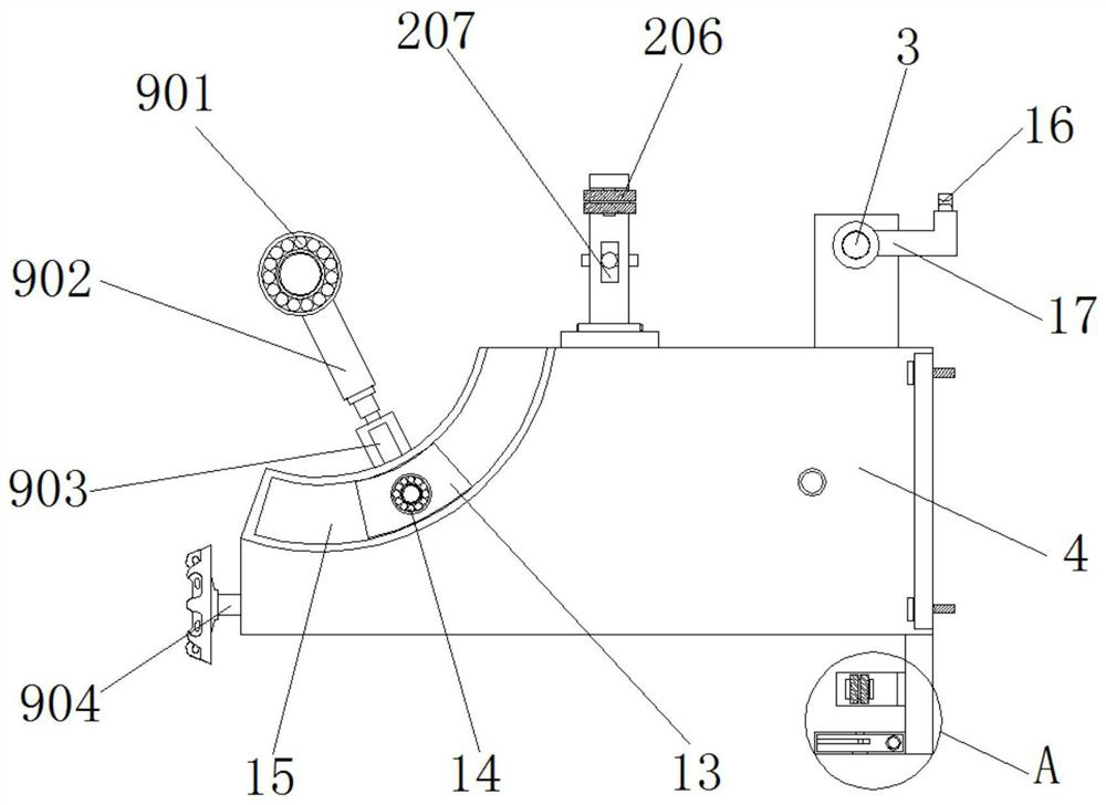
[0038] Example 1, as Figure 1-7 As shown in the figure, when the double twister starts to operate, the spool continuously winds the yarn, and the moving shaft 3 continuously moves left and right with the third thread inlet 16 and the L-shaped mounting frame 17, so that the yarn can be evenly It is wound on the outside of the reel, and during the left and right reciprocating movement of the moving shaft 3, the yarn located between the two sets of fourth wire pulleys 206 is constantly in close contact with the grooves of the two sets of fourth wire pulleys 206, and drives the The four wire pulleys 206 rotate, and when the textile thread enters the inside of the dedusting bin 603 and is twisted into a yarn, the textile thread is constantly rubbed against the bottom of the inner wall of the second thread inlet hole 606 due to the force generated by the rotation. At the same time, the inside of the suction pipe 602 is in a negative pressure state through an external suction device...

Embodiment 2

[0039] Example 2, as Figure 1-4 As shown, when the tightness of the yarn needs to be adjusted, the long threaded rod 904 is manually rotated to force the female threaded block 905 to move on the long threaded rod 904. If the female threaded block 905 moves to the end away from the arc-shaped chute 15, Then the limit bar frame 903 pushes the rotating shaft 7 and the arc slider 13 to move in the same direction, the rotating shaft 7 slides inside the limit bar frame 903, and the lift rod 902 is gradually extended, and the arc slider 13 Moving inside the arc-shaped chute 15 will also bring the third wire pulley 8 closer to the end of the second wire pulley 5, so that the actual distance of the yarn between the second wire pulley 5 and the guide plate 11 is shortened, and vice versa. The actual distance of the yarn between the second guide wheel 5 and the guide disc 11 also improves the tightness of the yarn, the operation is simple, and the tightness of the yarn after adjustment ...


PUM


Abstract

The invention discloses an environment-friendly two-for-one twisted yarn production S-shaped wire structure, which includes a driving shaft, a moving shaft and a main body frame. The top end of the inner bottom of the main body frame is provided with an arc-shaped chute, and the inside of the arc-shaped chute An arc-shaped slider is provided, and second bearings are symmetrically installed at the middle positions on both sides of the arc-shaped slider, and the inner sides of the two sets of second bearings are jointly installed with a rotating shaft, and both ends of the rotating shaft extend to the main frame outside. The invention forces the internal threaded block to move on the long threaded rod by manually rotating the long threaded rod. If the internal threaded block moves to the end away from the arc-shaped chute, the limit bar frame pushes the rotating shaft and the arc-shaped slider to the same direction. Direction movement, and the movement of the arc-shaped slider inside the arc-shaped chute will also move the end of the third guide wheel close to the second guide wheel, so that the actual distance of the yarn between the second guide wheel and the guide disc is shortened, On the contrary, the tightness of the yarn is improved, and the operator can adjust the third guide wheel to different positions at will.

Description

technical field [0001] The invention relates to the technical field of double-twisting machines, in particular to an S-shaped wire structure for producing an environment-friendly double-twisted yarn. Background technique [0002] The main purpose of twisted silk is to increase its strength and elasticity by adding twist to its filament. The scope of use of twisted silk includes: viscose twisted silk, polyester twisted silk, nylon twisted silk, silk twisted silk, etc. Variety, Jinsiyuan special silk is of high quality due to its latest development technology and non-steam vacuum setting. [0003] When the current double twister adjusts the tightness of the yarn through the wire structure, it is often necessary to manually move the wire wheel rotating shaft that adjusts the tightness to an appropriate position and then fix it. In the process of fixing the rotating shaft, the rotating shaft and the The position of the corresponding wire pulley is likely to be shifted, resultin...

Claims


Application Information

Patent Timeline
Patent Type & Authority Patents(China)
IPC IPC(8): D01H13/04D01H1/10D01H13/10
CPCD01H13/04D01H1/10D01H13/10D01H1/166D01H7/12D01H7/868D01H13/14
Inventor 茹秋利郭建洋陈业海刘菊沈大连赵慧娟
Owner JIANGSU DESHUN TEXTILES
Why Eureka
Try Eureka