Combined U-shaped beam structure for medium-low speed maglev traffic

A beam structure, U-shaped technology, used in bridges, bridge parts, bridge applications, etc., can solve the problems of large nonlinear temperature changes in the section, high rigidity requirements of the beam body, and large structure height, etc., to facilitate prestressing and shrinkage. Creep deformation, controlled prestress and shrinkage creep deformation, and the effect of large overall structural stiffness of the bridge

Pending Publication Date: 2022-01-21
CHINA RAILWAY ERYUAN ENG GRP CO LTD
View PDF9 Cites 1 Cited by
  • Summary
  • Abstract
  • Description
  • Claims
  • Application Information

AI Technical Summary

Problems solved by technology

[0008] 1. Since maglev vehicles often have to "hold the rail" to run, the lateral width of track beam A is controlled by the vehicle limit. In order to improve the bending stiffness of the track beam section and facilitate the installation of horizontal connecting beam B at the lower part of the double-track track beam, the beam height of track beam A Usually high, the height of the beam body is high and the cables and power supply rails are hung outside the beam body, the bridge landscape effect is poor;
[0009] 2. The beam body of track beam A is relatively narrow, and the steel bars of the rail platform are reserved on track beam A, so it is difficult to transport the frame on the beam by the equipment for transporting the frame. The curved section needs to be curved and often twisted. Track beam A usually adopts ground roads Transportation and crawler crane erection, in the case of poor ground road conditions, the construction is more difficult
[0010] 3. The power supply rail is exposed on the outside of the beam body, without protective measures, and there are great potential safety hazards
The beam body is narrow, there is no maintenance platform on the beam, and the maintenance and maintenance conditions during operation are poor;
[0011] 4. The track beam A is a closed section, and the uneven temperature change of the beam body section can easily cause the vertical deformation of the beam body, which is not conducive to the safe operation of the maglev train
[0012] 2. Large box girder
[0014] 1. Due to the high rigidity requirements of the beam body for the maglev vehicle, the height of the girder body of the large box girder C on the lower floor is relatively large, and the rail bearing beam D is superimposed on it, so the landscape effect of the beam body is poor;
[0015] 2. The beam body is large in size and the project economy is poor; the beam body is heavy and road transportation is difficult, and large-scale beam lifting equipment is required, and the construction load of the beam body transporting frame is relatively controlled for the bridge structure design;
[0016] 3. The beam type has poor adaptability to areas with large changes in line spacing. Since the maglev line needs to be opened at the position where the turnout is set and before and after the "island" station, the box room structure must be changed to adapt to the change of the line. , which is not conducive to the standardization and factoryization of bridge manufacturing and erection
[0017] 4. The whole-bore box girder is a closed section, and it is easy to produce uneven nonlinear temperature changes on the section. This change will cause the vertical deformation of the beam body, which is not conducive to the safe operation of the maglev train
[0018] To sum up, the beam types commonly used in maglev rail transit generally have defects such as large structural height, poor landscape effect, many constraints on frame transportation and construction, and large influence of nonlinear temperature changes on the cross-section. Problems such as poor adaptability of spacing

Method used


Image

  • Combined U-shaped beam structure for medium-low speed maglev traffic
  • Combined U-shaped beam structure for medium-low speed maglev traffic
  • Combined U-shaped beam structure for medium-low speed maglev traffic

Examples


Embodiment Construction

[0037] The present invention will be further described below in conjunction with the accompanying drawings and embodiments.

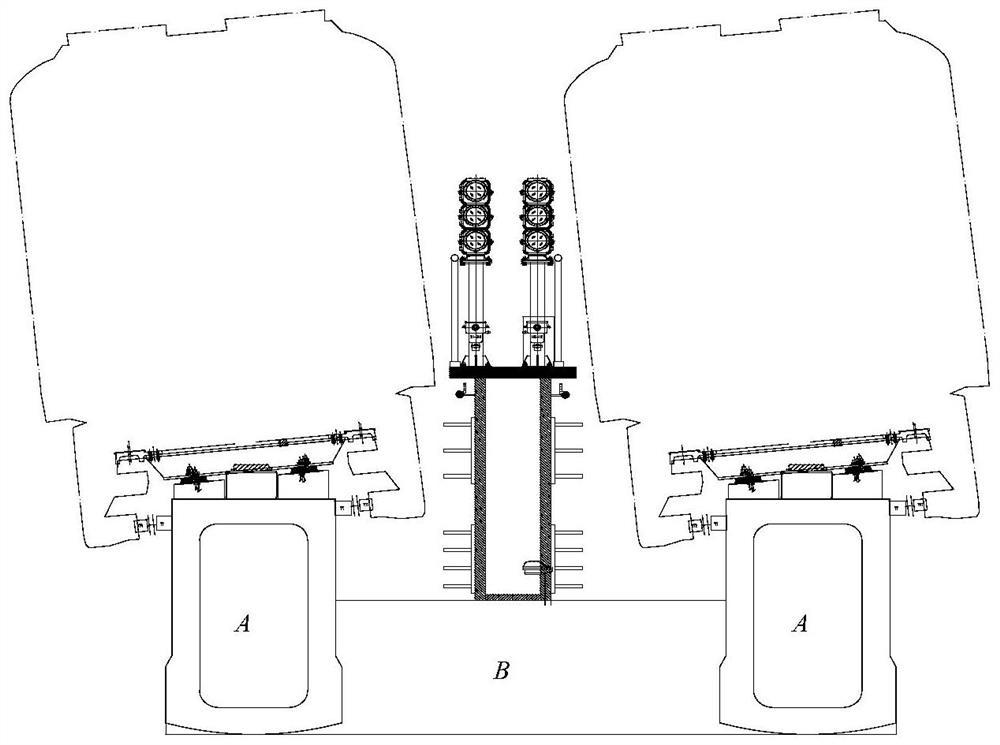
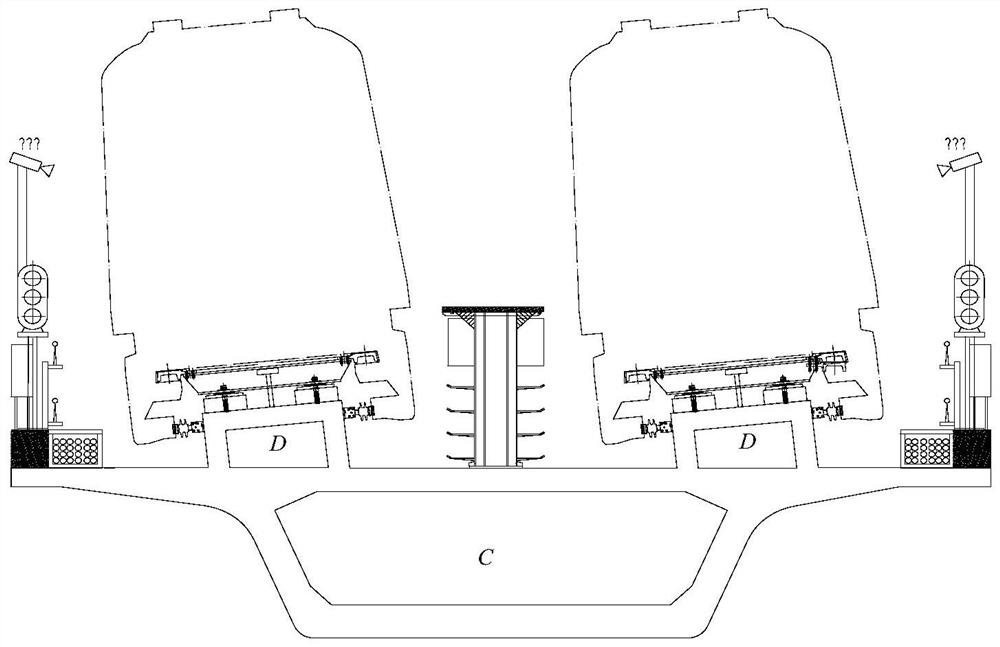
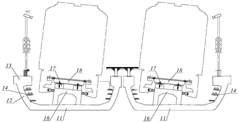
[0038] refer to Figure 4 , a combination U-shaped beam structure for medium and low-speed maglev transportation of the present invention is composed of a U-shaped beam and a supporting rail beam to form a combined structure. The section of the U-shaped beam is U-shaped, and has a U-shaped beam bottom plate 11 and a U-shaped beam web 12 on both sides. The lower end of the web 15 of the rail-supporting beam is fixedly connected with the bottom plate 11 of the U-shaped beam to form a whole, and the U-shaped beam and the rail-supporting beam are not provided with broken joints, forming a combined structure and jointly participating in the structural stress. The rail-bearing beam participates in the overall stress of the structure, which effectively improves the section stiffness of the beam body. The structure of the rail-bearing beam only needs to meet ...


PUM


Abstract

The invention relates to a combined U-shaped beam structure for medium-low-speed maglev traffic, wherein the structure is used for effectively reducing the height of a bridge, improving the landscape of the bridge, facilitating transportation, erection and construction, facilitating operation and maintenance and improving the adverse effect of temperature on the premise of meeting the requirements of rigidity, deformation and the like of a maglev train. A combined structure is formed by a U-shaped beam and a rail bearing beam, and the rail bearing beam continuously extends in the line direction. The section of the U-shaped beam is in a U shape, the U-shaped beam is provided with a U-shaped beam bottom plate and U-shaped beam webs on the two sides, the rail bearing beam is provided with a rail bearing beam top plate and rail bearing beam webs on the two sides, and the lower ends of the rail bearing beam webs on the two sides are fixedly connected with the U-shaped beam bottom plate to form a whole. Power supply rails are arranged on the outer walls of web plates of the rail bearing beams on the two sides, rail bearing tables are fixedly installed on top plates of the rail bearing beams, rail structures are fixedly installed on the rail bearing tables, and cable supports are fixedly installed on the inner walls of web plates of the U-shaped beams on the two sides.

Description

technical field [0001] The invention relates to bridge engineering, in particular to a combined U-shaped beam structure for medium and low speed maglev traffic. Background technique [0002] Maglev rail transit has the characteristics of strong climbing ability, small turning radius, no wear, and low noise. The train has high requirements on the rigidity of the beam body, and strict requirements on the deformation of the beam body, the manufacturing and installation accuracy of the track and the rail bearing beam. [0003] The structural form of the maglev bridge should be compatible with the operation mode of the maglev vehicle, and the bridge structure design should match the characteristics of the maglev rail transit itself. The maglev bridge should also be more environmentally friendly, landscape, mechanical performance, and construction convenience Therefore, the design of the bridge structure and the selection of materials should take into account noise reduction and ...

Claims


Application Information

Patent Timeline
Patent Type & Authority Applications(China)
IPC IPC(8): E01B25/30E01D18/00E01D19/00
CPCE01B25/30E01B25/305E01D18/00E01D19/00
Inventor 周永礼蒋彪杨林许志艳谢华易大伟伍磊鲁雪冬宋晓东陈峰艾智能唐正风袁立平戴礼勇
Owner CHINA RAILWAY ERYUAN ENG GRP CO LTD
Why Eureka
Try Eureka