Electronic control silicone oil clutch driving disc and clutch

A silicon oil clutch, active disc technology, applied in clutches, fluid clutches, machines/engines, etc., can solve the problems of slow separation speed, high fan idle speed, fan fault misjudgment, etc., and achieve time and speed control of accelerated engagement and separation High precision, accelerated meshing and separation effects

Pending Publication Date: 2022-01-21
DONGFENG BEHR THERMAL SYST
View PDF3 Cites 0 Cited by
  • Summary
  • Abstract
  • Description
  • Claims
  • Application Information

AI Technical Summary

Problems solved by technology

However, the cap structure itself will bring two problems: First, when the elasticity of the "returning elastic part" decays to a certain extent, the cap will not be able to close the oil port, the original designed oil blocking function will be completely invalid, and the "cold start" problem will recur ;Secondly, different fan types and different fan speeds have different centrifugal forces. The development of "centrifugal parts" is difficult and the platform has poor versatility. If the designed centrifugal force is too small, the cover cannot open the oil port, and the silicone oil cannot enter the work. cavities, the clutch will permanently disengage and the clutch will fail to function
[0009] When the silicone oil clutch enters the disengaged state, the silicone oil in the internal working cavity cannot flow into the oil storage cavity quickly, resulting in a slow separation speed. In addition, because part of the silicone oil is always retained in the working cavity, the silicone oil cannot completely enter the oil storage cavity, and the idle speed of the fan is high. Additional energy consumption for the engine cooling system
[0010] When the silicone oil clutch enters the meshing state, part of the silicone oil will stay in the oil storage chamber and cannot quickly fill the working chamber, resulting in long clutch response time, slow fan speed, and slow heat dissipation from the engine system. It will trigger the high temperature alarm of the engine, cause the panic of end customers, and even lead to misjudgment of after-sales fan failure
[0011] Due to the limitation of the internal oil circuit design of the clutch, the silicone oil cannot flow smoothly and steadily between the oil storage chamber and the working chamber, and often flows too fast or too slowly, resulting in low precision of the speed control of the silicone oil fan, for example: mainstream silicone oil fans There is generally a deviation of ±100rpm between the actual speed and the required speed, especially when the input speed of the engine is low, the deviation is particularly serious
[0012] The driving discs inside the mainstream clutches are all designed with a shaft, which is convenient for magnetic conduction in the clutch, but the shaft is subjected to continuous stress during use, so in the aftermarket, shaft breakage often occurs, which causes the clutch function to fail.

Method used


Image

  • Electronic control silicone oil clutch driving disc and clutch
  • Electronic control silicone oil clutch driving disc and clutch
  • Electronic control silicone oil clutch driving disc and clutch

Examples


Embodiment Construction

[0041] The present invention will be further described below in conjunction with the accompanying drawings and specific embodiments.

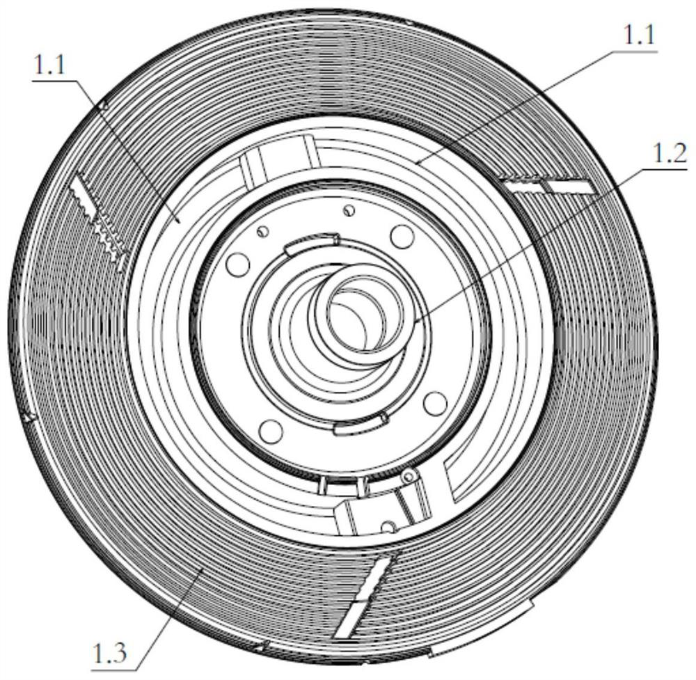
[0042] Such as figure 1 As shown, the existing clutch has a working cavity 1.3 arranged in the center of the driving disc and the edge of the driving disc, an oil storage chamber 1.1 is arranged between the working cavity 1.3 in the center of the driving disc and the edge of the driving disc, and an oil storage chamber 1.1 is arranged in the center of the driving disc. Drive disc central axis 1.2.

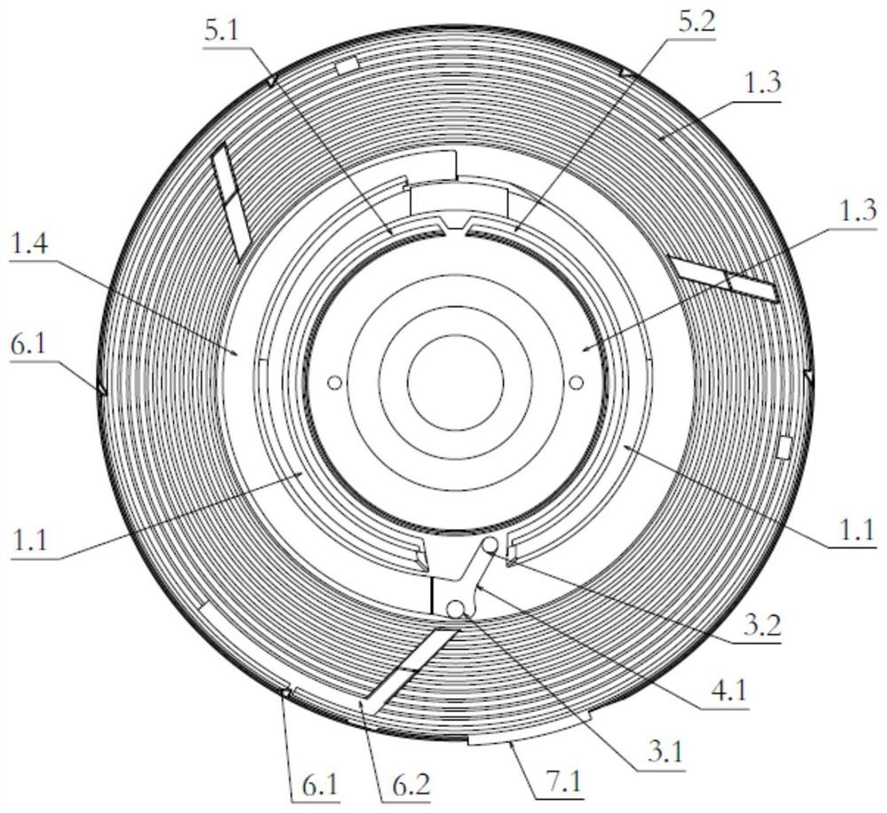
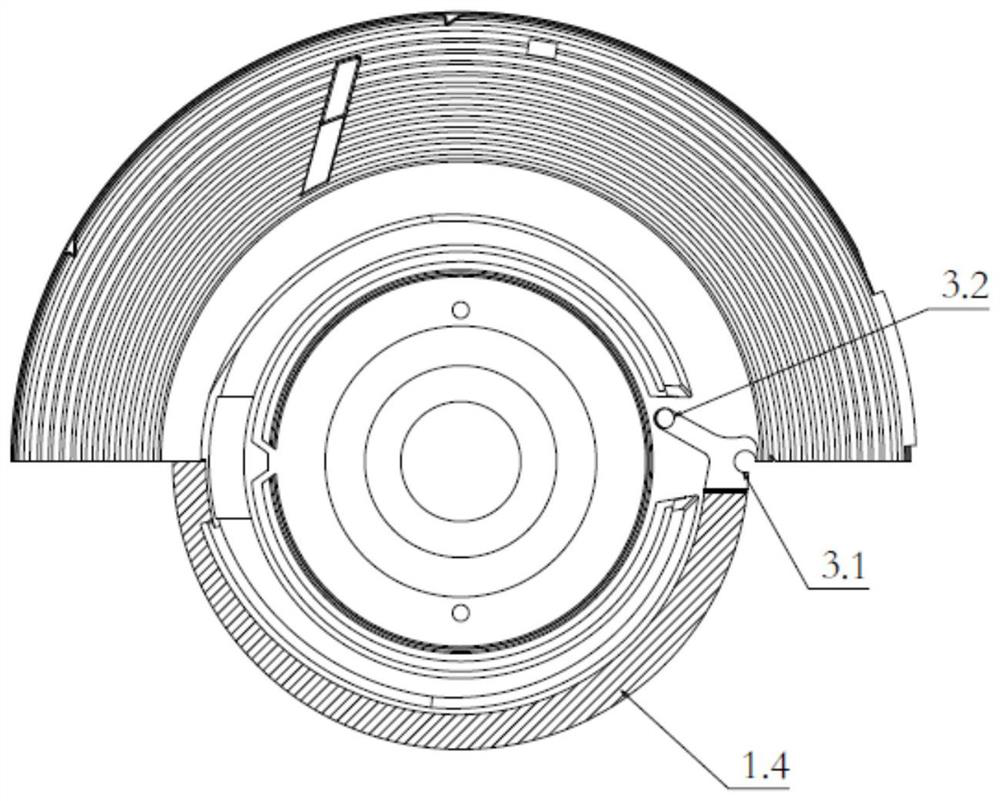
[0043] Such as Figure 2-6 As shown, the driving disc of an electronically controlled silicon oil clutch of the present invention is provided with an oil storage chamber 1.1, a working chamber 1.3, an oil outlet hole 3.1 and an oil return hole 3.2, and the oil storage chamber 1.1 and the working chamber 1.3 are closed According to the design, the silicone oil can only flow through the oil outlet hole 3.1 and the oil return hole 3.2; the oil storag...


PUM


Abstract

The invention relates to an electronic control silicone oil clutch driving disc and a clutch. An oil storage cavity, a working cavity, oil outlet holes and an oil return hole are formed in the driving disc, a two-way slope oil guide groove is formed between the oil storage cavity and the working cavity, and an oil guide groove opening in one end of the two-way slope oil guide groove is formed in the top of the oil storage cavity and communicates with the oil storage cavity; the other end of the two-way slope oil guide groove is arranged at an oil outlet hole and communicates with the oil outlet hole; and the two-way slope oil guide groove close to one end of the oil guide groove opening is narrow and deep, the two-way slope oil guide groove close to one end of the oil outlet hole is wide and shallow, and the whole two-way slope oil guide groove is in slope shape. According to the electronic control silicone oil clutch driving disc and the clutch, when the whole vehicle is static, no centrifugal force exists in the clutch, silicone oil is difficult to flow from a terminal of a low horizontal plane to the oil outlet hole of a high horizontal plane, and the amount of the silicone oil flowing into the working cavity is effectively reduced through the slope type design; and when the whole vehicle is in a working state, the slope type design plays a flow guide role due to the centrifugal force, the silicone oil is accelerated to flow out of the oil outlet holes, and the meshing time is shortened.

Description

technical field [0001] The invention relates to a commercial vehicle engine cooling system, in particular to an electronically controlled silicone oil clutch driving disc and a clutch. Background technique [0002] The heat dissipation of the engine cooling system of the commercial vehicle platform is mainly completed through radiators, intercoolers, cooling fans, etc. Among them, the cooling fan has developed from the direct-connected fan that could not be adjusted in the early stage, to the electromagnetic fan with limited gear adjustment, and recently to the electronically controlled silicon oil fan that can realize infinitely variable speed. Fast development. Silicon oil fans currently on the market include temperature-controlled and electronically controlled silicone oil fans, among which electronically controlled silicone oil fans are gradually becoming the first choice for major commercial vehicle platforms due to their precise control and quick response. [0003] T...

Claims


Application Information

Patent Timeline
Patent Type & Authority Applications(China)
IPC IPC(8): F16D35/02F01P7/04
CPCF16D35/02F16D35/024F01P7/042
Inventor 王宁彭斯李东平吴志鹏江扬帆郑恒
Owner DONGFENG BEHR THERMAL SYST
Why Eureka
Try Eureka