
Current comparison circuit and image sunspot effect detection device and method

A current comparison and circuit technology, applied in the field of image sensors, can solve the problems of small photoelectric signals, pixel leakage reset voltage, reduction, etc., to achieve the effect of low power consumption

Pending Publication Date: 2022-01-21
CHENGDU LIGHT COLLECTOR TECH
View PDF8 Cites 0 Cited by
  • Summary
  • Abstract
  • Description
  • Claims
  • Application Information

AI Technical Summary

Problems solved by technology

Based on the current pixel (Pixel) technology and the CIS control timing of the most widely used SS-ADC architecture, the sunspot effect will appear in the strong light source, which will cause the pixel to leak electricity after reset and reduce the reset voltage, resulting in the overall small or even small photoelectric signal collected. zero

Method used


Image

  • Current comparison circuit and image sunspot effect detection device and method
  • Current comparison circuit and image sunspot effect detection device and method
  • Current comparison circuit and image sunspot effect detection device and method

Examples


Embodiment Construction

[0052] In order to make the purpose, technical solutions and advantages of the present invention clearer, the technical solutions in the embodiments of the present invention will be clearly and completely described below in conjunction with the accompanying drawings of the present invention. Obviously, the described embodiments are part of the present invention Examples, not all examples. Based on the embodiments of the present invention, all other embodiments obtained by persons of ordinary skill in the art without creative efforts fall within the protection scope of the present invention. Unless otherwise defined, the technical terms or scientific terms used herein shall have the usual meanings understood by those skilled in the art to which the present invention belongs. As used herein, "comprising" and similar words mean that the elements or items appearing before the word include the elements or items listed after the word and their equivalents, without excluding other el...


PUM


Abstract

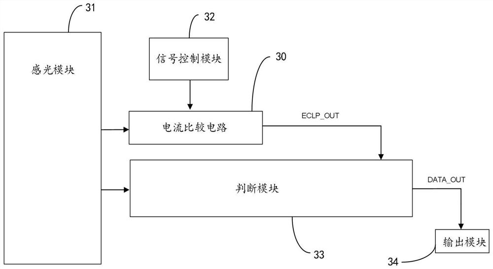
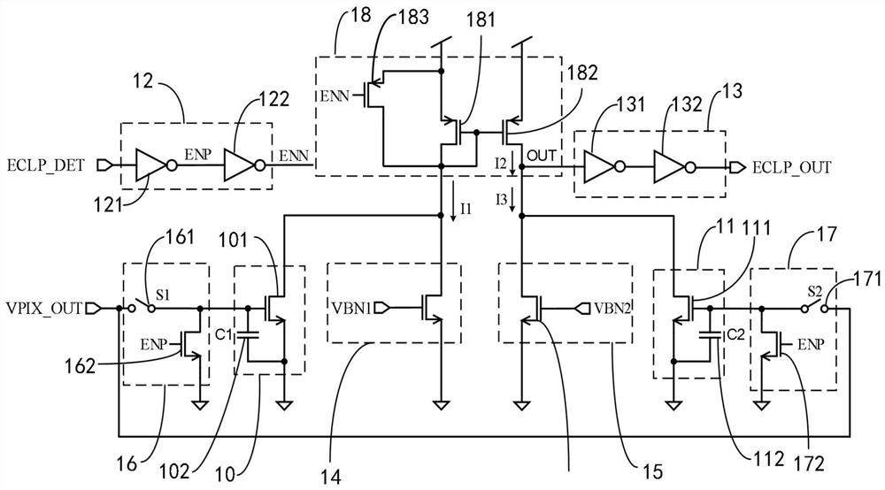
The invention provides a current comparison circuit and an image sunspot effect detection device and method. The image sunspot effect detection device comprises the current comparison circuit, a light sensing module, a signal control module and a judgment module, and the light sensing module is used for outputting pixel voltage signals according to image signals; the current comparison circuit is connected with the photosensitive module and is used for carrying out current detection and comparison on the output end of the photosensitive module; the signal control module is connected with the current comparison circuit and is used for providing a control signal for the current comparison circuit; the judgment module is connected with the output end of the light sensing module and the output end of the current comparison circuit and used for conducting image sunspot judgment according to comparison signals of the current comparison circuit, whether the sunspot effect exists in an image or not can be rapidly detected through simple logic control, and meanwhile the overall circuit is low in power consumption.

Description

technical field [0001] The invention relates to the technical field of image sensors, in particular to a current comparison circuit, a device and a method for detecting the sunspot effect of an image. Background technique [0002] Complementary Metal-Oxide-Semiconductor (CMOS) refers to a technology used to manufacture large-scale integrated circuit chips or chips manufactured by this technology, and CMOS image sensors (CMOS Image Sensors) based on this chip technology Sensor, CIS), as an image sensing device, is irreplaceable in the image field, and as CMOS image sensor chips are more and more widely used, in order to show stable and reliable output images in various scenarios, The performance requirements of corresponding products are getting higher and higher. [0003] Among the various indicators of the CIS chip, the stability of the output image under strong light sources is the basic requirement of various CIS products, especially the CIS for vehicle applications, whi...

Claims


Application Information

Patent Timeline
IPC IPC(8): G01R19/165G06K9/00
CPCG01R19/16533G06F2218/00
Inventor 芮松鹏蔡化陈飞陈正夏天王勇
Owner CHENGDU LIGHT COLLECTOR TECH
Learn More