Projection equipment

A technology of projection equipment and convex lens, which is applied in the directions of optics, instruments, projection devices, etc., and can solve the problems of large volume of projection equipment and poor display effect of projection images

Pending Publication Date: 2022-01-21
QINGDAO HISENSE LASER DISPLAY CO LTD
View PDF0 Cites 1 Cited by
  • Summary
  • Abstract
  • Description
  • Claims
  • Application Information

AI Technical Summary

Problems solved by technology

[0006] The present application provides a projection device, which can solve the problems that the display eff

Method used


Image

  • Projection equipment
  • Projection equipment
  • Projection equipment

Examples


Embodiment Construction

[0020] In order to make the purpose, technical solution and advantages of the present application clearer, the implementation manners of the present application will be further described in detail below in conjunction with the accompanying drawings.

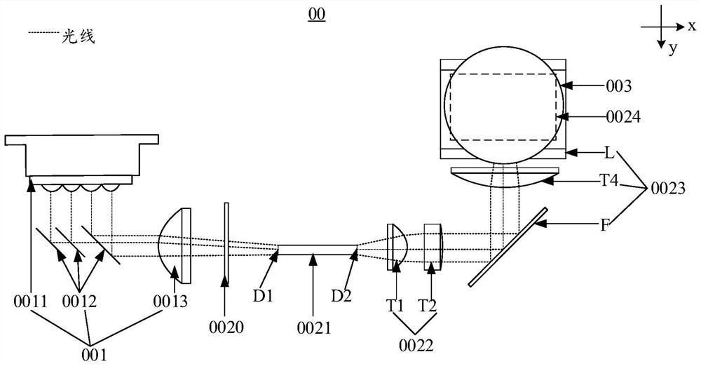
[0021] With the development of optoelectronic technology, the requirement for miniaturization of projection equipment is getting higher and higher. figure 1 It is a structural schematic diagram of a projection device provided by the related art. Such as figure 1 As shown, the projection device 00 may include: a light source 001, an optical machine ( figure 1 Not marked), lens 003. The light source 001 may include a laser 0011 , a combination lens group 0012 and a converging lens 0013 . The laser 0011 can emit light (such as red, green and blue three-color lasers) to the combined lens group 0012, and the combined lens group 0012 can mix the light emitted by the laser 0011, and send the mixed light to the converging lens 0013 ,...


PUM


Abstract

The invention discloses projection equipment, and belongs to the technical field of photoelectricity. The projection equipment comprises a light source, a light valve, a lens, a first convex lens located in a light path between the light source and the light valve, a first diffusion sheet, a second convex lens and a dodging component, wherein the focuses of the first convex lens and the second convex lens coincide, the coincident focuses are located between the first convex lens and the second convex lens, the first diffusion sheet is located at the focus, the first convex lens is used for converging light rays emitted by the light source to the first diffusion sheet, the first diffusion sheet is used for expanding the divergence angle of the incident light rays and then emitting the incident light rays to the second convex lens, the second convex lens is used for emitting the incident light rays to the dodging component, the dodging component is used for dodging the incident light rays and then emitting the light rays to the light valve, and the light spot area on the first convex lens is larger than that on the second convex lens. According to the invention, the problem that the display effect of the projection picture of the projection equipment is poor is solved; and the equipment is used for projection.

Description

technical field [0001] The present application relates to the field of optoelectronic technology, in particular to a projection device. Background technique [0002] With the development of optoelectronic technology, the requirements for the display effect of the projection screen of the projection device are getting higher and higher. [0003] figure 1 It is a structural schematic diagram of a projection device provided by the related art. Such as figure 1 As shown, the projection device 00 includes: a light source 001 , a light guide 0021 , an illumination mirror group 0022 , a light valve 0024 , and a lens 003 . The light pipe 0021 is strip-shaped, and the light entrance D1 and the light exit D2 of the light pipe 0021 are located in its length direction (such as figure 1 in the x direction) at both ends. The light source 001 injects light into the light inlet D1 of the light guide 0021 , the light guide 0021 homogenizes the light transmitted therein, and the light is...

Claims


Application Information

Patent Timeline
IPC IPC(8): G03B21/20G02B27/48G02B27/09
CPCG03B21/208G03B21/2033G02B27/48G02B27/0955
Inventor 李巍颜珂田有良
Owner QINGDAO HISENSE LASER DISPLAY CO LTD
Why Eureka
Try Eureka