
Cooling fan blade device

A cooling air and cooling fan technology, which is applied to cooling/ventilation devices, electromechanical devices, electrical components, etc., can solve the problems of inability to effectively control and reduce the temperature rise of the motor, poor cooling effect of the cooling fan blades, and increase the manufacturing cost of the motor, etc. Achieve the effect of improving cooling effect, improving quality of use and improving production efficiency

Inactive Publication Date: 2022-01-21
安徽舟水电器有限公司
View PDF0 Cites 0 Cited by
  • Summary
  • Abstract
  • Description
  • Claims
  • Application Information

AI Technical Summary

Problems solved by technology

[0002] After the motor is energized, it runs at a high speed. The wire packs of the armature assembly and the stator assembly are energized to generate loss and heat to generate temperature rise. In order to control the temperature rise of the motor within a reasonable range, it is necessary to install cooling blades for cooling; the existing The cooling effect of the cooling fan blade is poor, and it is impossible to effectively control and reduce the temperature rise of the motor. At the same time, the existing cooling fan blade cannot increase the airflow directed to the motor part during operation, and the airflow of the motor at high speed will generate relatively large noise. , which reduces the quality of use of the motor; because the high-speed operation of the motor rotor drives the cooling fan to rotate, the centrifugal force is extremely high, and the cooling fan needs to be made of metal to ensure the strength, thereby ensuring that the cooling fan will not be deformed or even caused by centrifugal force when the cooling fan is running at high speed. The role of cooling fan blades will not cause tearing, which increases the cost of motor manufacturing and reduces production efficiency

Method used


Image

  • Cooling fan blade device
  • Cooling fan blade device
  • Cooling fan blade device

Examples


Embodiment Construction

[0017] In the present invention, unless otherwise clearly specified and limited, terms such as "installation", "connection", "connection" and "fixation" should be understood in a broad sense, for example, it can be a fixed connection or a detachable connection , or integrated; can be mechanically connected, can also be electrically connected or can communicate with each other; can be directly connected, can also be indirectly connected through an intermediary, can be the internal communication of two components or the interaction relationship between two components, unless expressly defined otherwise. Those of ordinary skill in the art can understand the specific meanings of the above terms in the present utility model according to specific situations.

[0018] In the present invention, unless otherwise clearly specified and limited, the first feature may be in direct contact with the first feature or the first and second feature may be in direct contact with the second featur...


PUM


Abstract

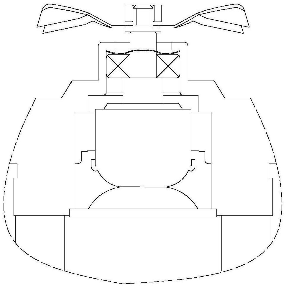
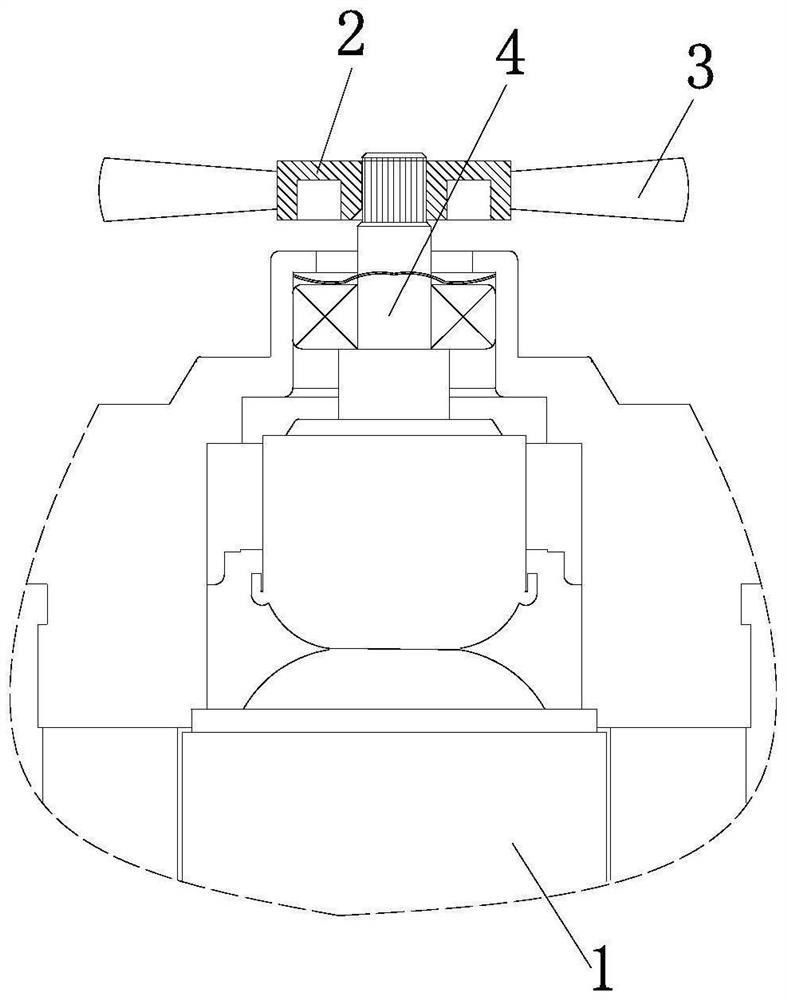
The invention provides a cooling fan blade device, which comprises a motor and a cooling fan arranged on the motor, a fixing ring is arranged on the motor, the cooling fan comprises a fixing ring and a plurality of cooling fan blades, and one end parts of the plurality of cooling fan blades are distributed along the circumferential direction of the fixing ring and are arranged on the outer circumference of the fixing ring. According to the invention, the design is novel, the operation is simple, by setting the shape, size and number of the cooling fan blades, the cooling effect of the cooling fan blades can be improved, the temperature rise of the motor can be effectively controlled and reduced, the airflow guided to the motor part is increased, the noise generated by the airflow in high-speed operation of the motor is reduced, and the use quality of the motor is improved; and the cooling fan blade is made of nylon and glass fiber materials, and the cooling fan blade is integrally processed through injection molding, so that the operation strength of the cooling fan blade is ensured, the cooling fan blade is ensured not to be deformed and torn during high-speed operation, the manufacturing cost of the motor is reduced, and the production efficiency is improved.

Description

technical field [0001] The invention relates to the technical field of motor cooling, in particular to a cooling fan device. Background technique [0002] After the motor is energized, it runs at a high speed. The wire packs of the armature assembly and the stator assembly are energized to generate loss and heat to generate temperature rise. In order to control the temperature rise of the motor within a reasonable range, it is necessary to install cooling blades for cooling; the existing The cooling effect of the cooling fan blade is poor, and it is impossible to effectively control and reduce the temperature rise of the motor. At the same time, the existing cooling fan blade cannot increase the airflow directed to the motor part during operation, and the airflow of the motor at high speed will generate relatively large noise. , which reduces the quality of use of the motor; because the high-speed operation of the motor rotor drives the cooling fan to rotate, the centrifugal...

Claims


Application Information

Patent Timeline
Patent Type & Authority Applications(China)
IPC IPC(8): H02K9/06
CPCH02K9/06H02K2213/03
Inventor 金海平聂李刚潘青文戴亿万罗丹
Owner 安徽舟水电器有限公司
Learn More