Sealed screening machine

A technology of screening machine and sealing ring, applied in the direction of filter screen, solid separation, grille, etc., can solve the problem that the screening machine cannot achieve continuous feeding and closed screening, reduce large-area contact, prevent dust flashing, The effect of reducing pollution

Pending Publication Date: 2022-01-25
沈阳商溢达科技有限公司
View PDF0 Cites 0 Cited by
  • Summary
  • Abstract
  • Description
  • Claims
  • Application Information

AI Technical Summary

Problems solved by technology

[0005] Purpose of the invention: The present invention proposes a sealed screening machine, the purpose of which is to solve the problem that the existing screening machine cannot realize continuous feeding and closed screening

Method used


Image

  • Sealed screening machine
  • Sealed screening machine
  • Sealed screening machine

Examples


Embodiment 1

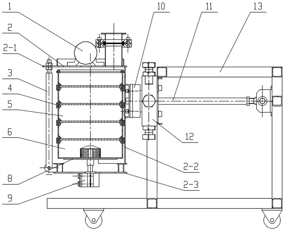
[0030] Such as Figure 1-2 As shown, a sealed screening machine, the vibrating screen main body of the screening machine is installed on the suspension support frame body, the vibrating screen main body includes a vibrating motor 1, a screen frame 2, a locking device, a special sieve tray 5, and a sieve tray seat 6, The sieve frame 2 is fixed on the suspension support frame body, the upper plate 2-1 of the sieve frame 2 is provided with a sample loading interface 7, and the sieve frame 2 is provided with a vibrating motor 1, and the present invention does not limit the specific setting position of the vibrating motor 1 In this example, the vibrating motor 1 is arranged on the top of the screen frame 2, and can also be arranged at any position such as the bottom of the screen frame 2, the side, etc., and its purpose is to provide a source of vibration for the main body of the vibrating screen. The sieve frame 2 is provided with a plurality of special sieve trays 5 which are sna...

Embodiment 2

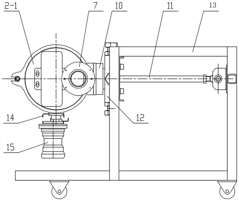
[0045] The overall structure is substantially the same as that of Embodiment 1, except that the front column is canceled by changing the surrounding angle of the side plate 2-2, which makes it easier to take and place the special sieve tray 5 and the sieve tray seat 6, such as image 3 shown.

[0046] Instructions:

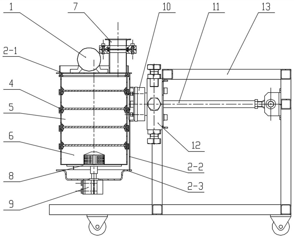
[0047] Unlock the locking cylinder 9, directly fit the sieve tray seat 6 and multiple special sieve trays 5 from bottom to top and place the special sealing ring 4 and the top sealing ring 5-3, open the locking cylinder 9, and pass the locking cylinder 9 piston rod Push the sieve tray seat 6 and multiple special sieve trays 5 together with the top sealing ring 4 and the top top sealing ring 5-3 to move up and press the upper plate 2-1 at the same time to realize the sieve tray seat 6 and multiple special sieve trays 5 The fixing and sealing between them ensure the overall stability of the main body of the vibrating screen. Through the movement of the vibrating m...


PUM


Abstract

The invention relates to a sealed screening machine. A vibration sieve main body of the screening machine is installed on a suspension supporting frame body and comprises a vibration motor, a sieve frame, a locking device, special sieve trays and a sieve tray base, wherein the sieve frame is fixed to the suspension supporting frame body, a sample feeding connector is arranged on an upper plate of the sieve frame, the vibration motor is arranged on the sieve frame, a plurality of special sieve trays which are sequentially clamped in a sealed mode are arranged in the sieve frame, the sieve tray base is connected below the special sieve tray on the lowest layer in a sealed and clamped mode, discharging ports are formed in the special sieve trays and the sieve tray base, and the locking device is arranged on the sieve frame. According to the sealed screening machine, the problem that an existing screening machine cannot achieve continuous feeding and closed screening is solved.

Description

technical field [0001] The invention relates to the technical field of screening machines, in particular to a sealed screening machine. Background technique [0002] Generally, many samples used for physical and chemical performance analysis in the laboratory are massive solids with different sizes. Therefore, after the laboratory receives the samples to be analyzed, it first needs to pulverize the samples. In the screening process, samples of different particle sizes are separated, or samples of required particle size are screened out. During the screening process, there are few screening machines that can completely isolate oxygen, and there is no closed screening machine that can continuously feed materials. This will lead to the oxidation of easily oxidized samples during the screening process, resulting in inaccurate experimental results and large errors. [0003] In the previous sieving process, a small amount of sample dust would float out into the sample preparation...

Claims


Application Information

Patent Timeline
Patent Type & Authority Applications(China)
IPC IPC(8): B07B1/28B07B1/42B07B1/46
CPCB07B1/28B07B1/42B07B1/4609B07B2201/04
Inventor 王哲王章丞
Owner 沈阳商溢达科技有限公司
Why Eureka
Try Eureka